Block diagrams of gas detection systems
Auxiliary materials for the design of gas detection systems
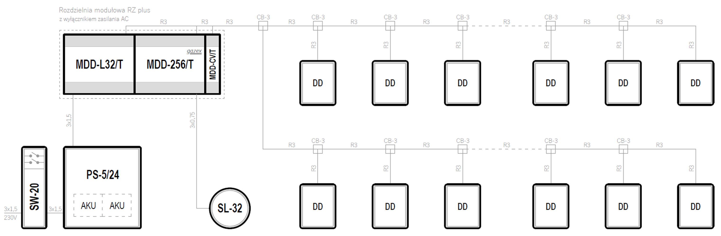
Battery rooms
| System topology | Supply voltage | Maximum number of gas detectors | Emergency power backup | |
|---|---|---|---|---|
| Star | 230VAC | 2 | — | Preview PDF DWG |
| Star | 230VAC | 4 | — | Preview PDF DWG |
| Star | 230VAC | 8 | — | Preview PDF DWG |
Fuel depots
| System topology | Supply voltage | Maximum number of gas detectors | Emergency power backup | |
|---|---|---|---|---|
| Star | 24VDC | 8 | ✓ | Preview PDF DWG |
| Star | 24VDC | 16 | ✓ | Preview PDF DWG |
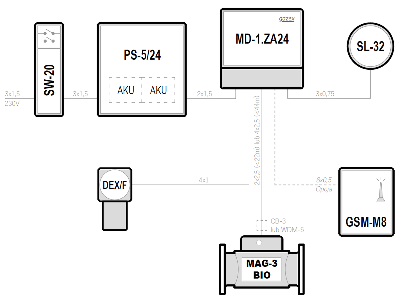
Biogas plants
| System topology | Supply voltage | Maximum number of gas detectors | Emergency power backup | |
|---|---|---|---|---|
| Star | 230VAC | 1 | ✓ | Preview PDF DWG |
| Star | 230VAC | 2 | — | Preview PDF DWG |
| Star | 230VAC | 4 | — | Preview PDF DWG |
| Star | 24VDC | 1 | ✓ | Preview PDF DWG |
Breweries and bottlers of carbonated drinks
| System topology | Supply voltage | Maximum number of gas detectors | Emergency power backup | |
|---|---|---|---|---|
| Star | 230VAC | 2 | — | Preview PDF DWG |
| Star | 230VAC | 4 | — | Preview PDF DWG |
| Bus | 24VDC | 224 | — | Preview PDF DWG |
Refrigeration
Ammonia plants
| System topology | Supply voltage | Maximum number of gas detectors | Emergency power backup | |
|---|---|---|---|---|
| Star | 230VAC | 2 | — | Preview PDF DWG |
| Star | 230VAC | 4 | — | Preview PDF DWG |
| Bus | 24VDC | 224 | — | Preview PDF DWG |
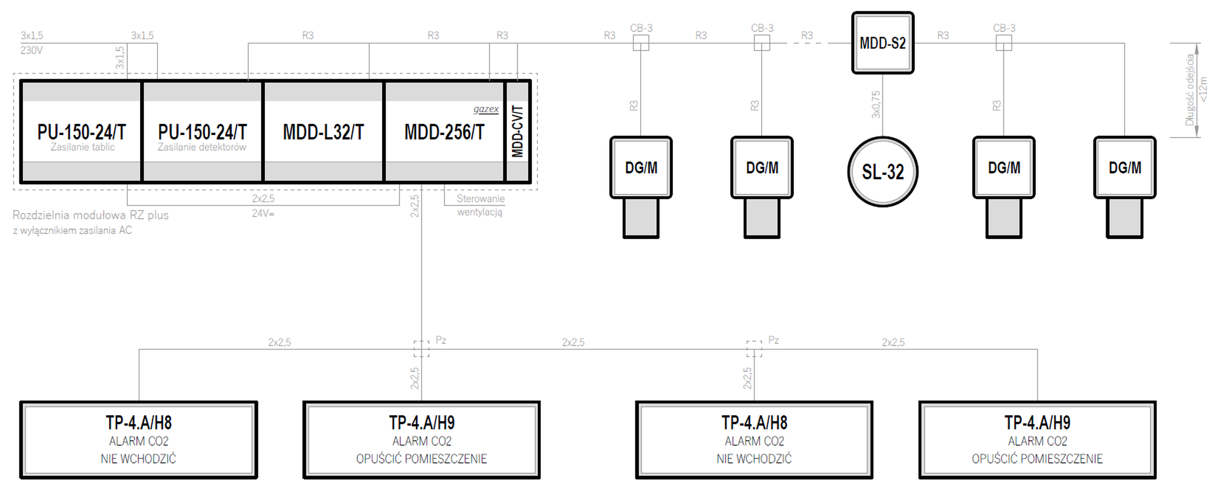
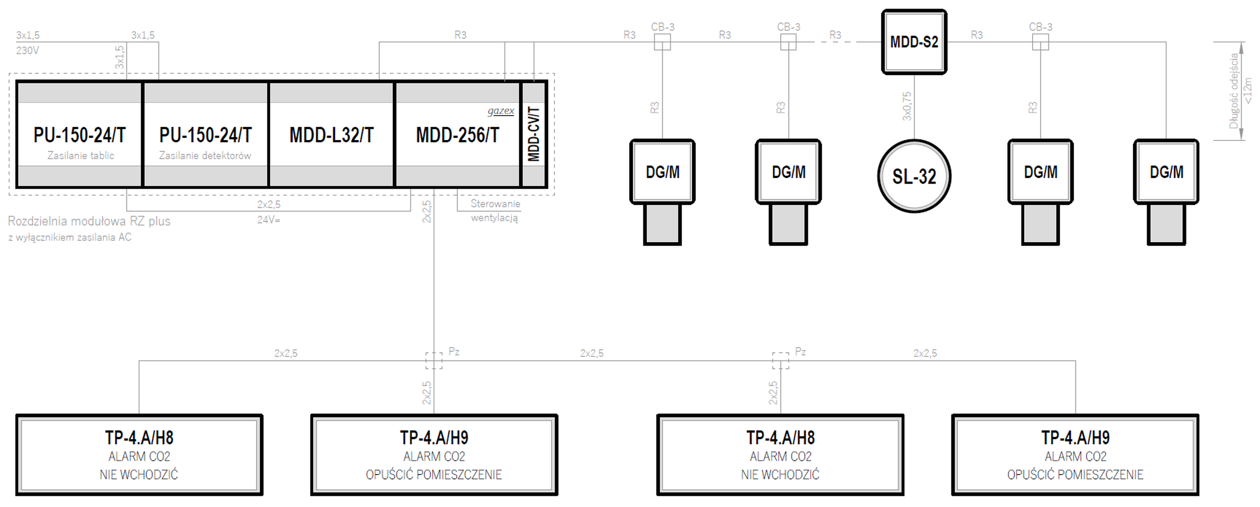
Carbon dioxide
| System topology | Supply voltage | Maximum number of gas detectors | Emergency power backup | |
|---|---|---|---|---|
| Serial (linear) | 230VAC | ∞ | — | Preview PDF DWG |
| Bus | 24VDC | 224 | — | Preview PDF DWG |
CFC, HCFC, HFC, HC, HFO
| System topology | Supply voltage | Maximum number of gas detectors | Emergency power backup | |
|---|---|---|---|---|
| Star | 230VAC | 2 | — | Preview PDF DWG |
| Star | 230VAC | 4 | — | Preview PDF DWG |
| Bus | 24VDC | 224 | — | Preview PDF DWG |
Garages, parking halls, workshops, service stations
Cars (garages, workshops, service stations)
| System topology | Supply voltage | Maximum number of gas detectors | Emergency power backup | |
|---|---|---|---|---|
| Serial (linear) | 230VAC | ∞ | — | Preview PDF DWG |
| Bus | 24VDC | 224 | — | Preview PDF DWG |
| Bus | 24VDC | 224 | — | Preview PDF DWG |
Trucks, buses (parking areas, workshops, service stations)
| System topology | Supply voltage | Maximum number of gas detectors | Emergency power backup | |
|---|---|---|---|---|
| Serial (linear) | 230VAC | ∞ | — | Preview PDF DWG |
| Bus | 24VDC | 224 | — | Preview PDF DWG |
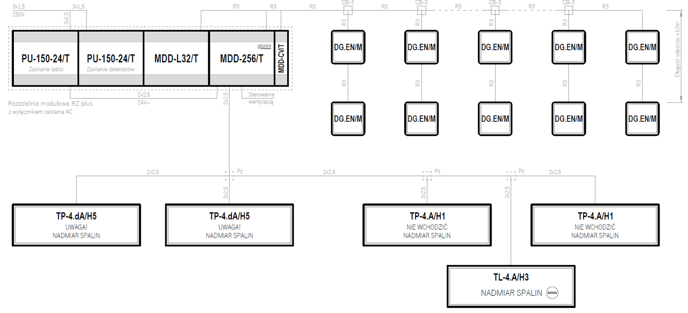
Halls equipped with gas heaters or radiant heaters
| System topology | Supply voltage | Maximum number of gas detectors | Emergency power backup | |
|---|---|---|---|---|
| Bus | 24VDC | 224 | — | Preview PDF DWG |
| Bus | 24VDC | 224 | — | Preview PDF DWG |
Air conditioning in public buildings
Detection of refrigerant leakage
| System topology | Supply voltage | Maximum number of gas detectors | Emergency power backup | |
|---|---|---|---|---|
| Bus | 24VDC | 224 | ✓ | Preview PDF DWG |
| Bus | 24VDC | 224 | — | Preview PDF DWG |
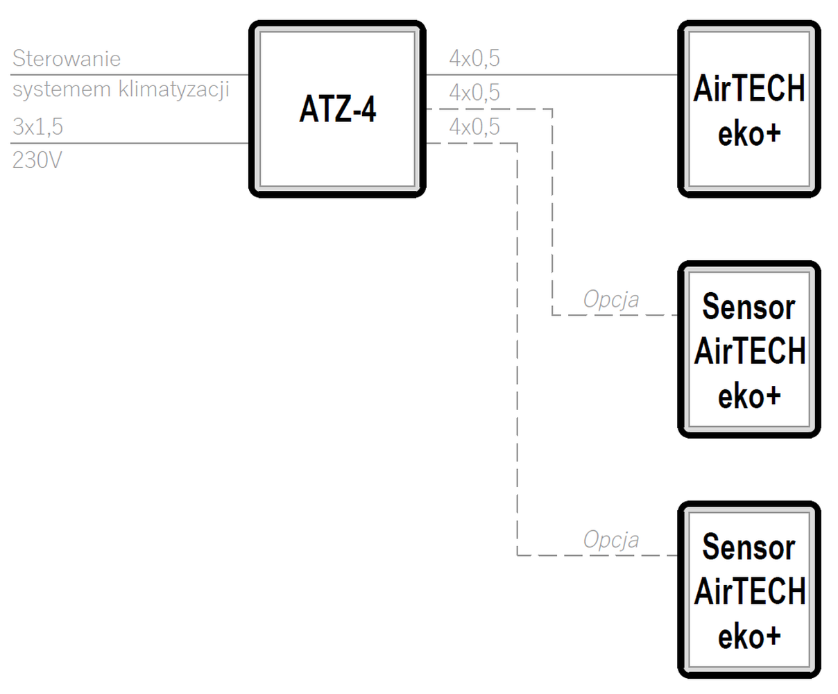
Air quality control (duct air conditioning)
| System topology | Supply voltage | Maximum number of gas detectors | Emergency power backup | |
|---|---|---|---|---|
| Star | 230VAC | 3 | — | Preview PDF DWG |
| Bus | 24VDC | 224 | — | Preview PDF DWG |
| Bus | 24VDC | 224 | — | Preview PDF DWG |
Gas boiler rooms
Low and medium power (DN32÷DN100 gas connections)
| System topology | Supply voltage | Maximum number of gas detectors | Emergency power backup | |
|---|---|---|---|---|
| Star | 230VAC | 1 | ✓ | Preview PDF DWG |
| Star | 230VAC | 1 | — | Preview PDF DWG |
| Star | 24VDC | 1 | ✓ | Preview PDF DWG |
Industrial and high power (≥DN125 gas connections)
| System topology | Supply voltage | Maximum number of gas detectors | Emergency power backup | |
|---|---|---|---|---|
| Star | 230VAC | 1 | — | Preview PDF DWG |
| Star | 230VAC | 4 | — | Preview PDF DWG |
| Star | 24VDC | 1 | ✓ | Preview PDF DWG |
Cryochambers
| System topology | Supply voltage | Maximum number of gas detectors | Emergency power backup | |
|---|---|---|---|---|
| Star | 230VAC | 1 | ✓ | Preview PDF DWG |
| Star | 12VDC | 2 | ✓ | Preview PDF DWG |
| Serial (linear) | 230VAC | ∞ | — | Preview PDF DWG |
Kitchens
| System topology | Supply voltage | Maximum number of gas detectors | Emergency power backup | |
|---|---|---|---|---|
| Star | 230VAC | 2 | — | Preview PDF DWG |
| Star | 230VAC | 4 | — | Preview PDF DWG |
| Star | 12VDC | 2 | ✓ | Preview PDF DWG |
Gas and chemical storage facilities
Chemical storage facilities
| System topology | Supply voltage | Maximum number of gas detectors | Emergency power backup | |
|---|---|---|---|---|
| Star | 230VAC | 4 | — | Preview PDF DWG |
| Bus | 24VDC | 224 | ✓ | Preview PDF DWG |
Gas storage facilities
| System topology | Supply voltage | Maximum number of gas detectors | Emergency power backup | |
|---|---|---|---|---|
| Star | 24VDC | 8 | ✓ | Preview PDF DWG |
| Bus | 24VDC | 224 | ✓ | Preview PDF DWG |
Wastewater treatment plants
| System topology | Supply voltage | Maximum number of gas detectors | Emergency power backup | |
|---|---|---|---|---|
| Star | 230VAC | 2 | — | Preview PDF DWG |
| Star | 12VDC | 4 | ✓ | Preview PDF DWG |
| Bus | 24VDC | 224 | ✓ | Preview PDF DWG |
LPG filling stations
| System topology | Supply voltage | Maximum number of gas detectors | Emergency power backup | |
|---|---|---|---|---|
| Star | 230VAC | 1 | — | Preview PDF DWG |
| Star | 230VAC | 4 | — | Preview PDF DWG |
| Star | 24VDC | 1 | ✓ | Preview PDF DWG |
Rozlewnie gazu płynnego
| System topology | Supply voltage | Maximum number of gas detectors | Emergency power backup | |
|---|---|---|---|---|
| Star | 230VAC | 4 | — | Preview PDF DWG |
| Star | 230VAC | 8 | — | Preview PDF DWG |
| Bus | 24VDC | 224 | ✓ | Preview PDF DWG |
Water treatment plants
| System topology | Supply voltage | Maximum number of gas detectors | Emergency power backup | |
|---|---|---|---|---|
| Star | 230VAC | 1 | — | Preview PDF DWG |
| Star | 230VAC | 2 | — | Preview PDF DWG |
| Star | 230VAC | 4 | — | Preview PDF DWG |
Healthcare facilities
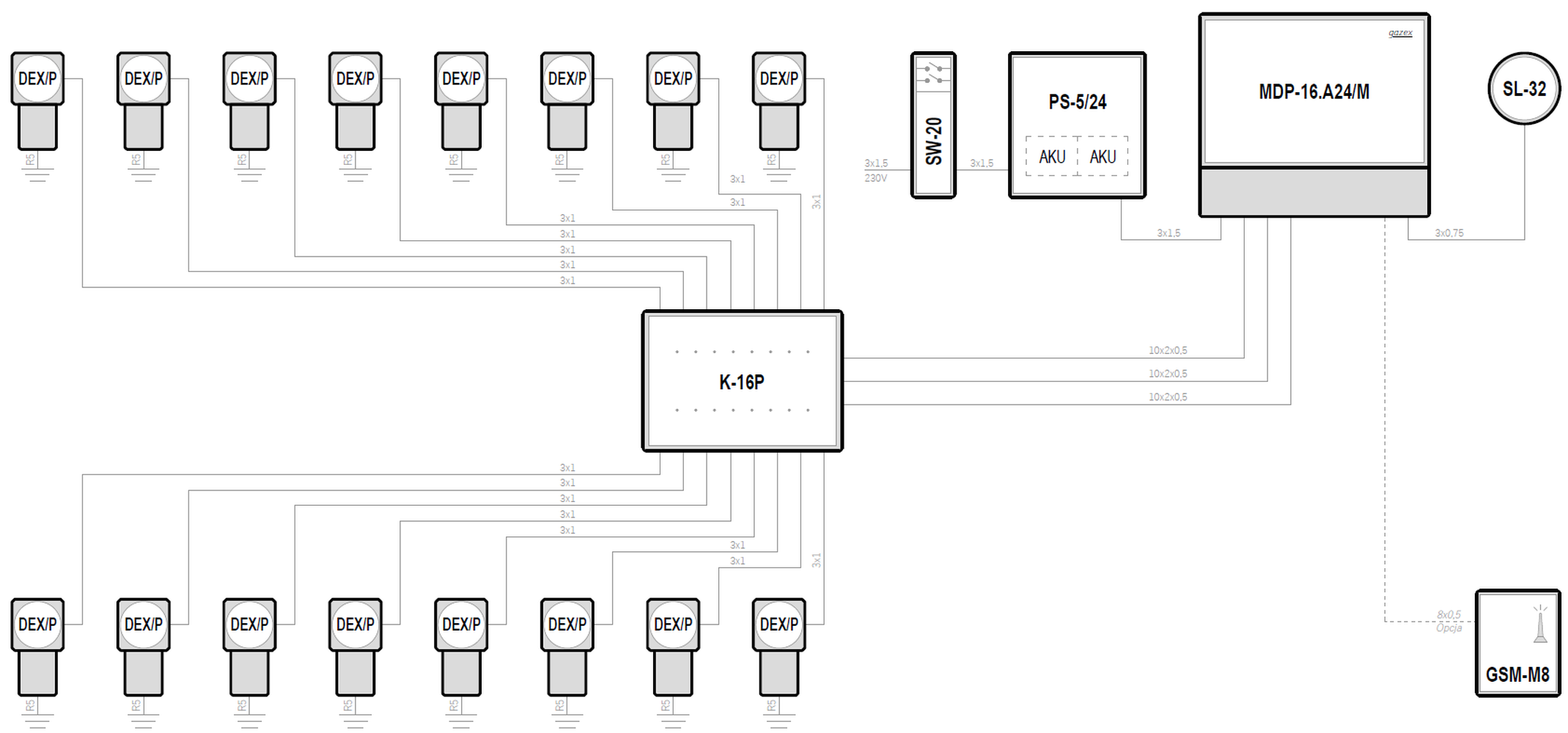
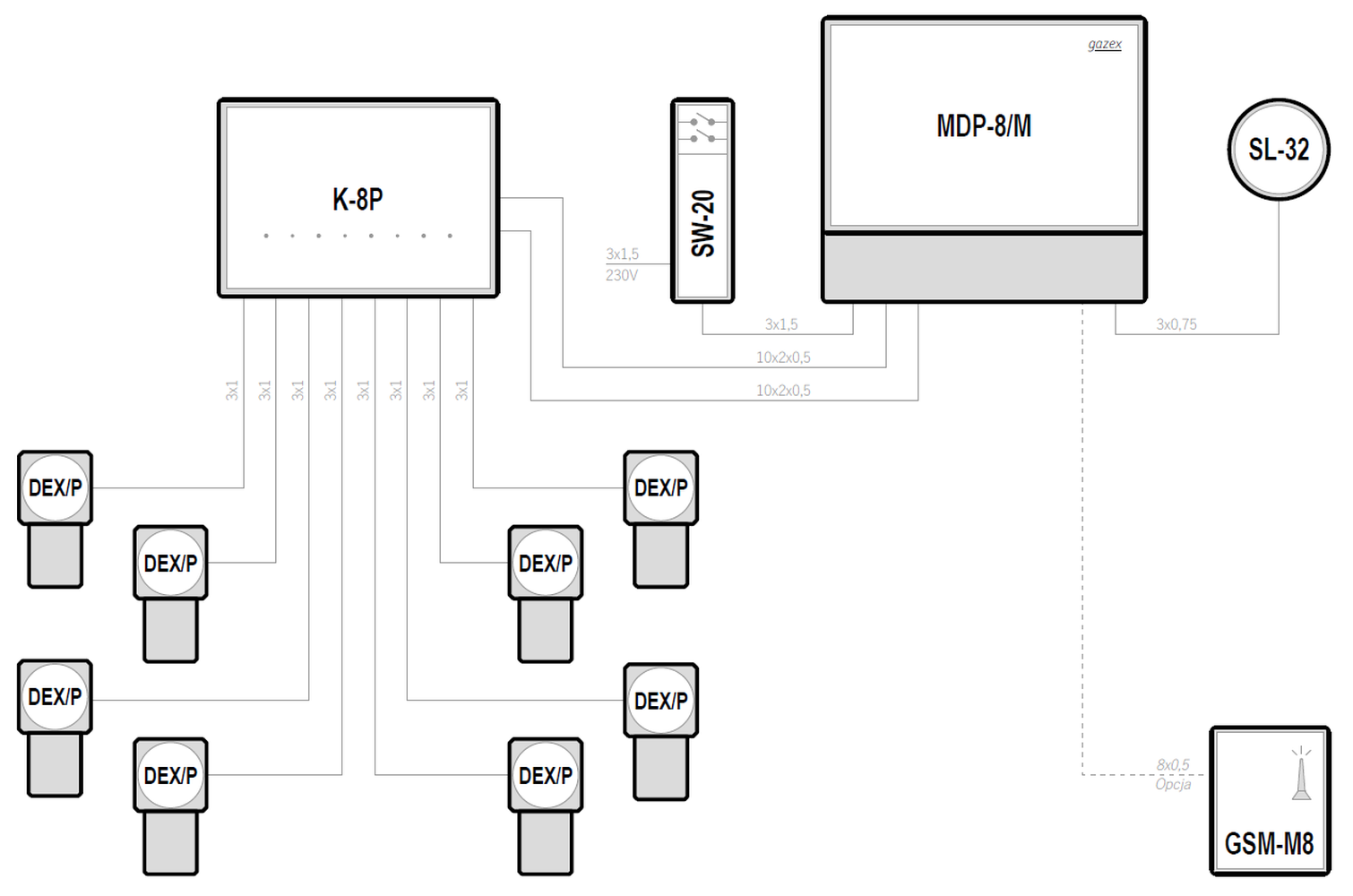
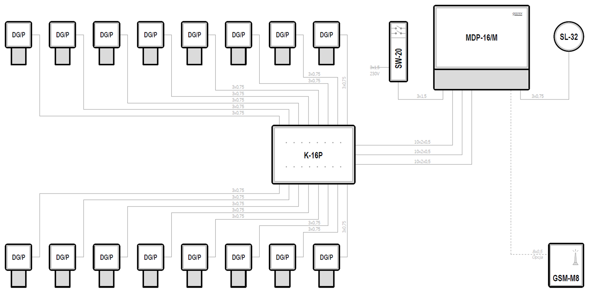
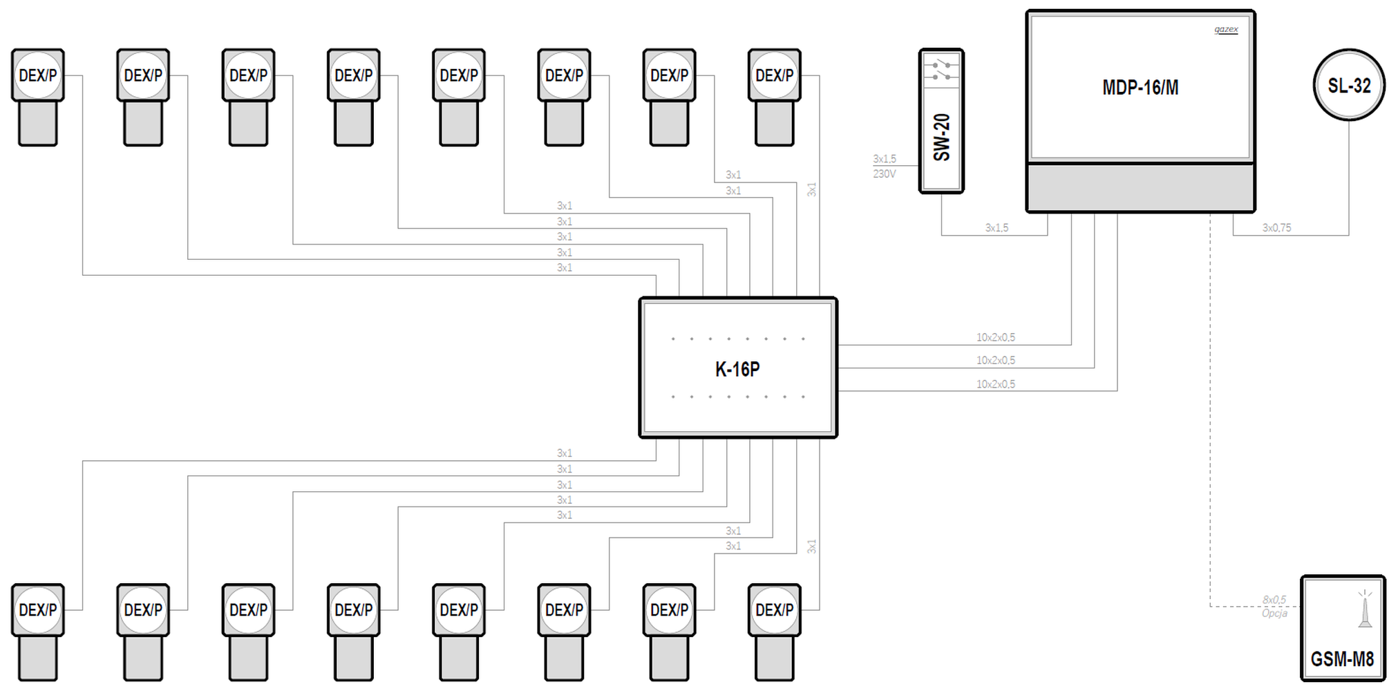
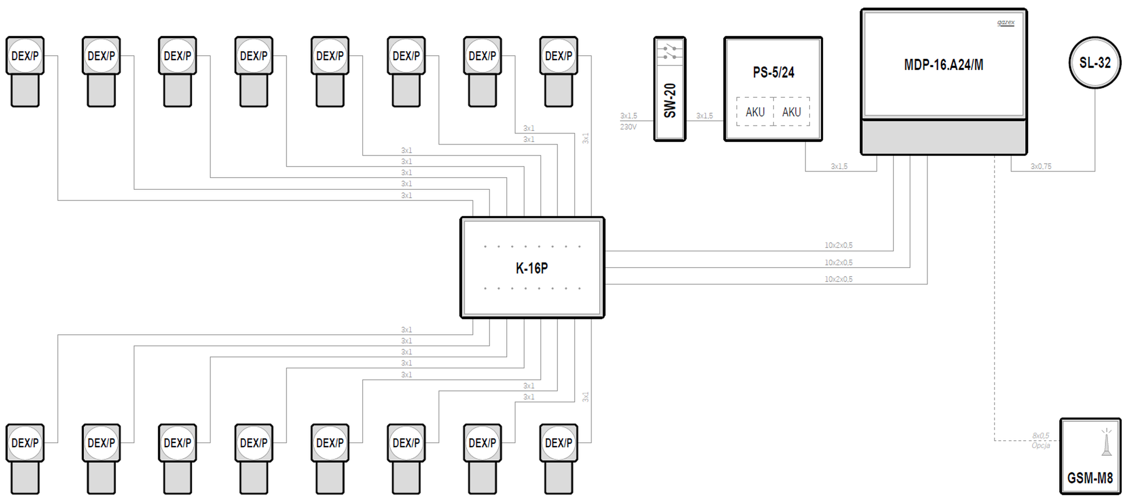
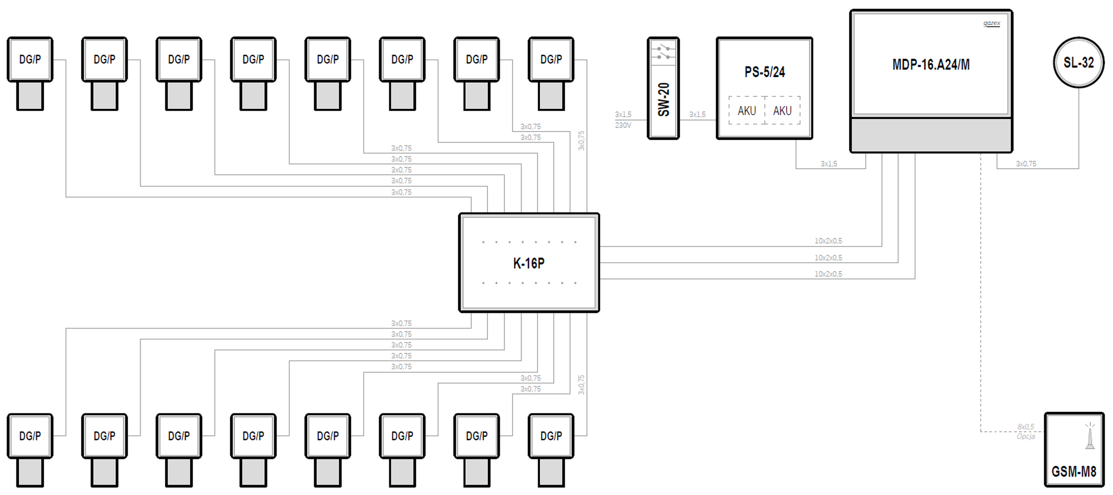
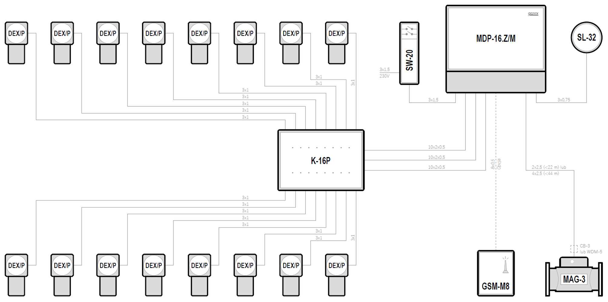
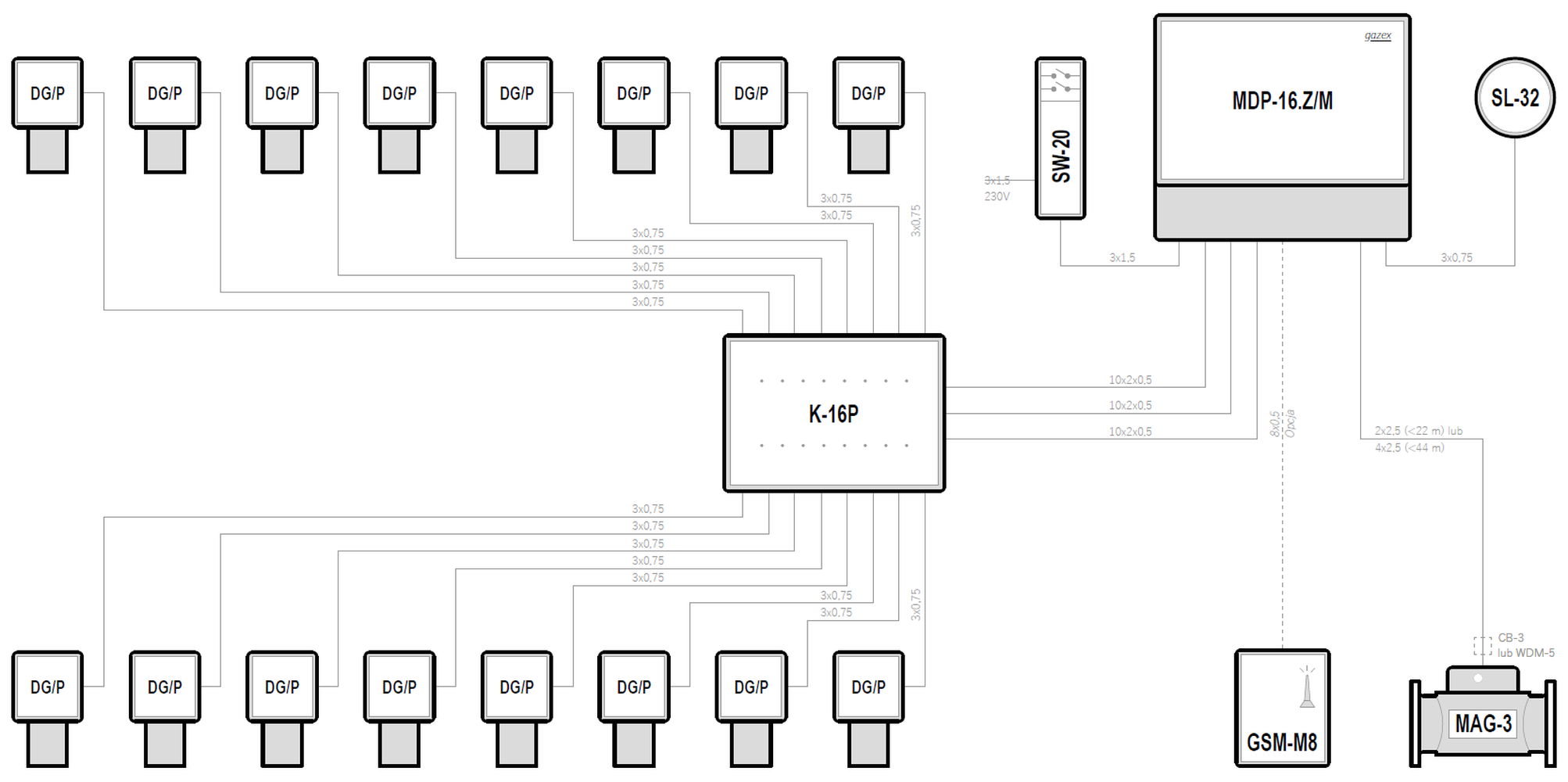
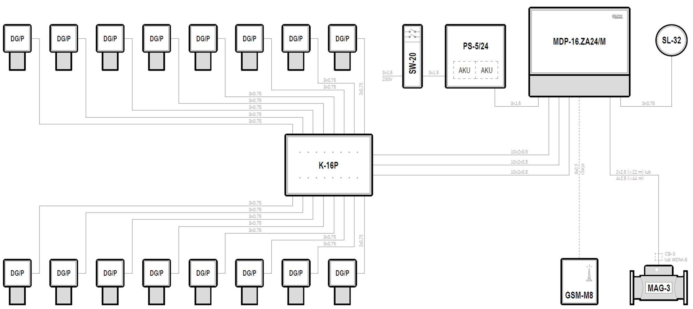
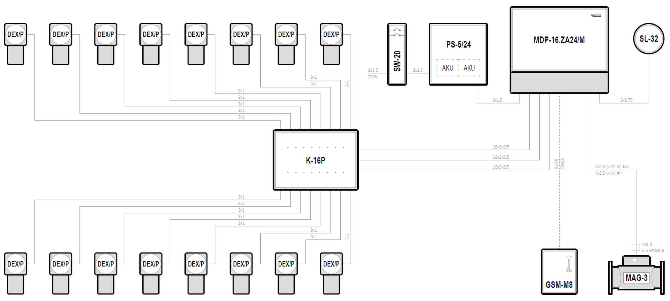
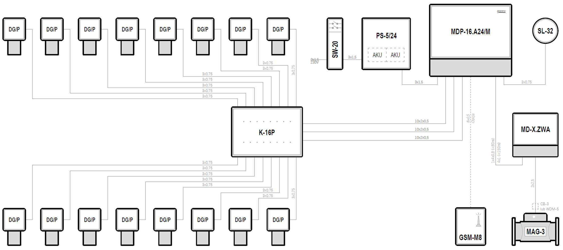
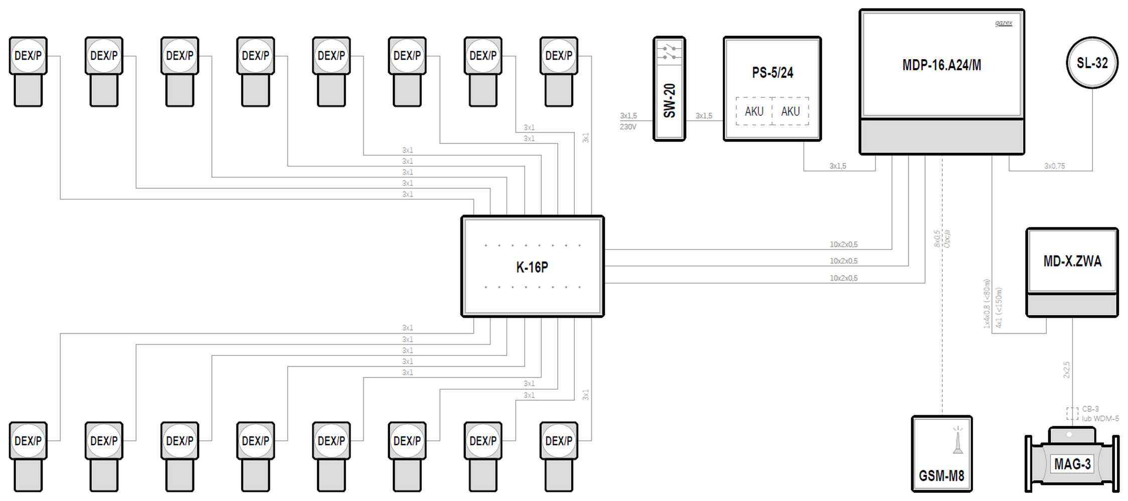
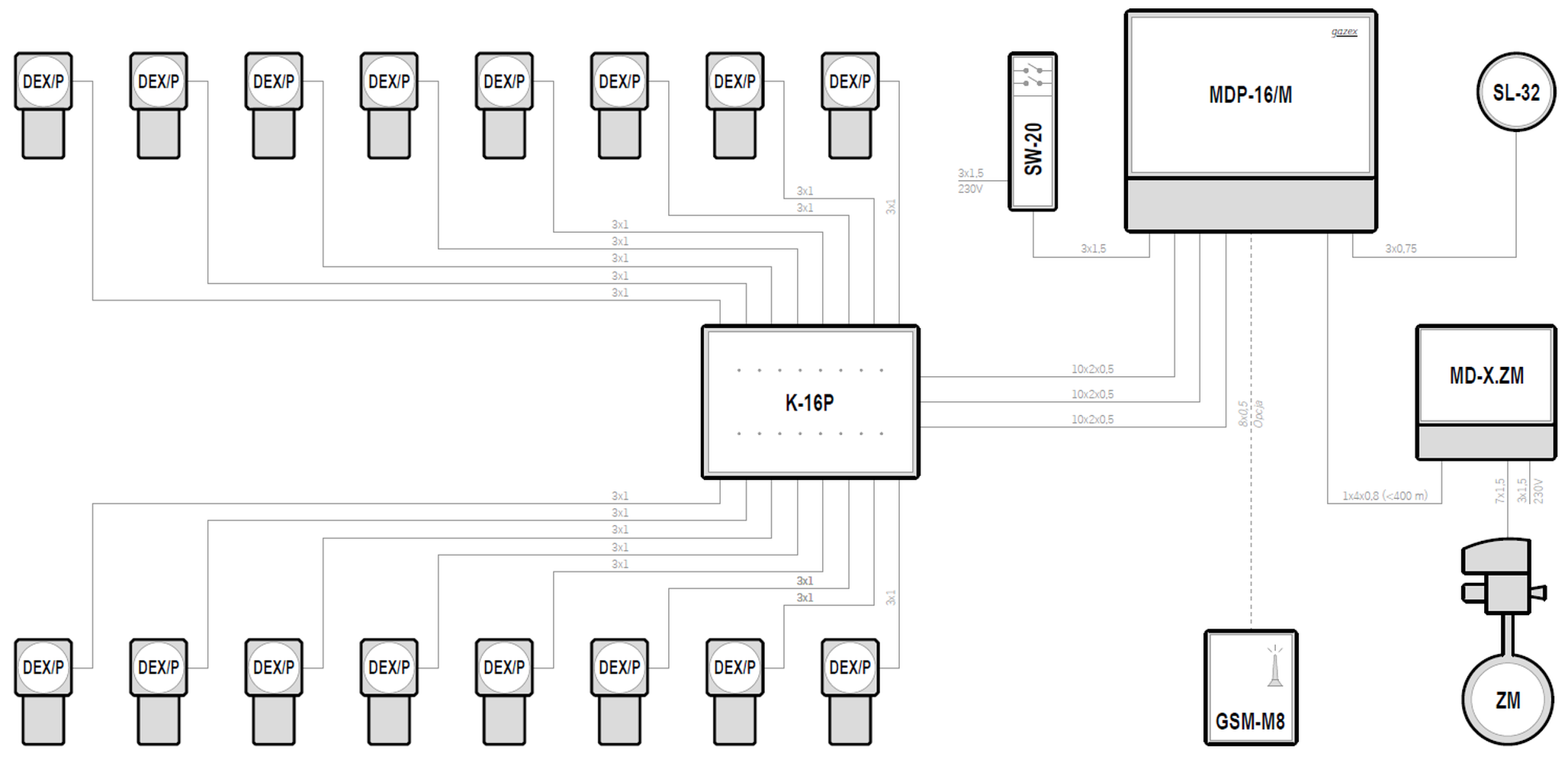
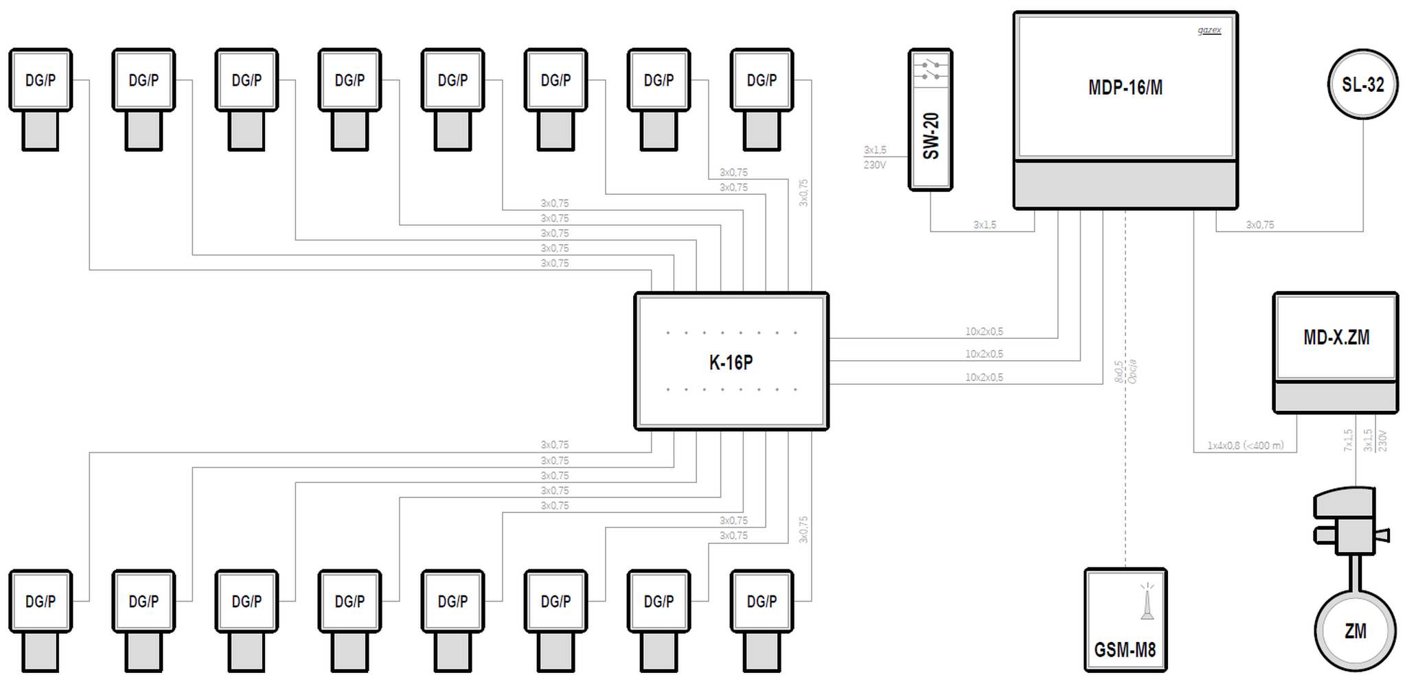
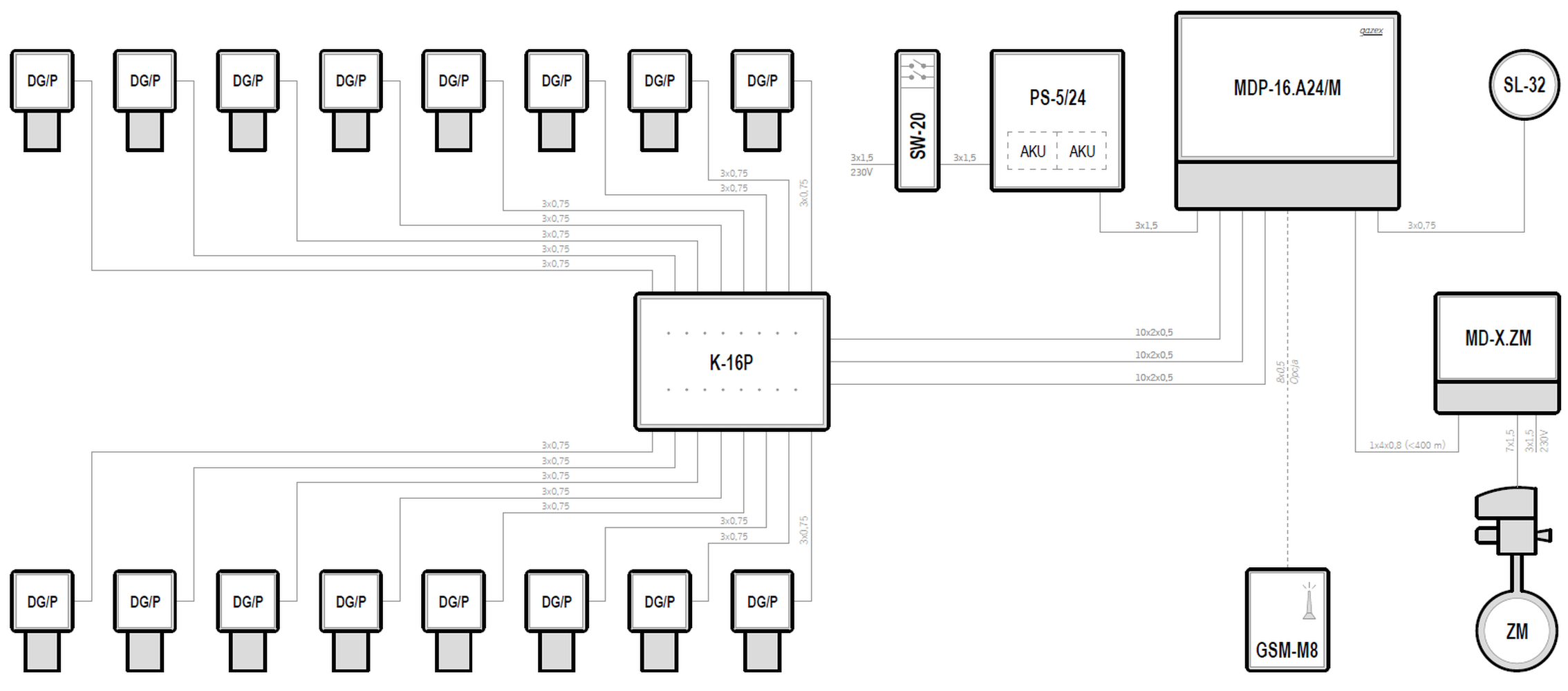
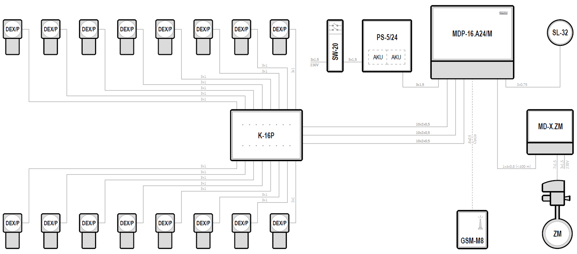
Systemy w oparciu o moduły sterujące typu MDP-16
| Supply voltage | Control unit | Maximum number of gas detectors | Types of gas detectors | Emergency power backup | |
|---|---|---|---|---|---|
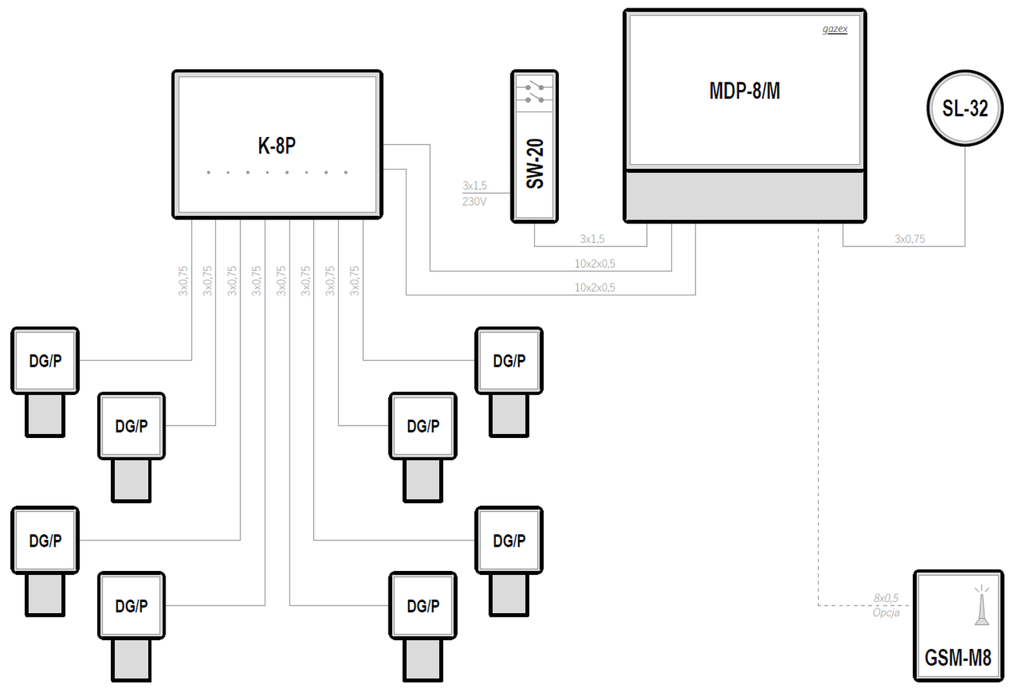
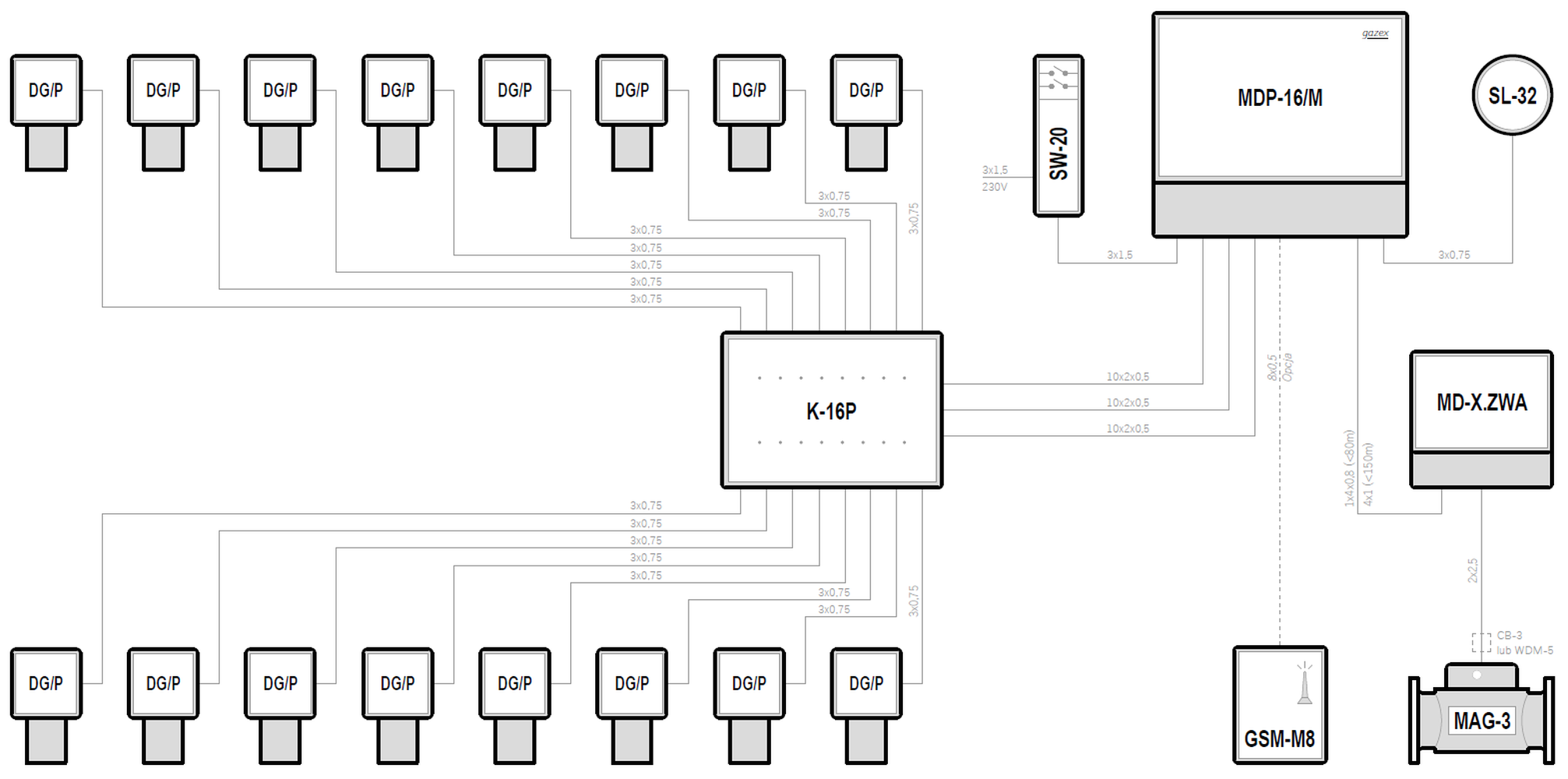
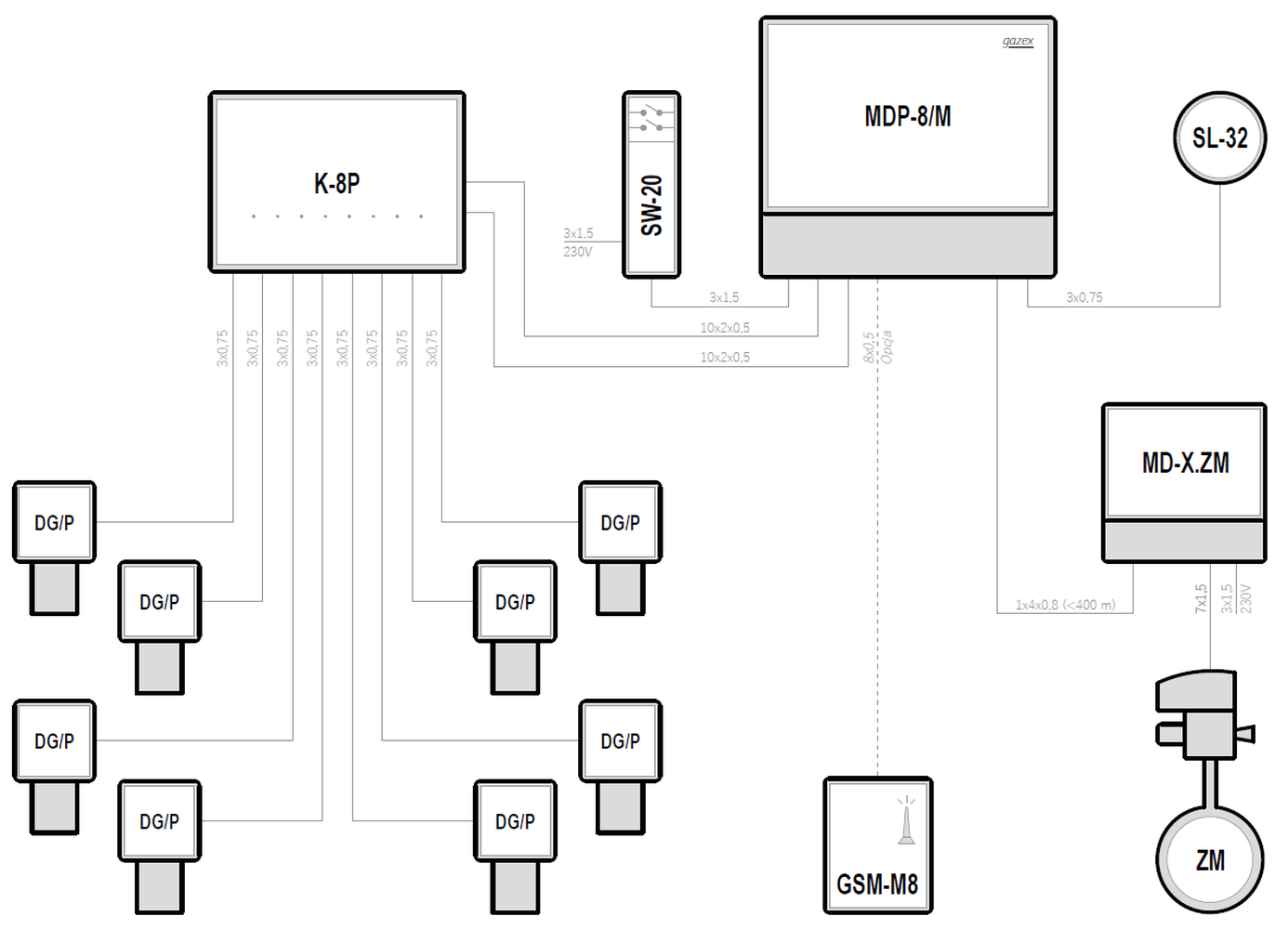
| 230VAC | MDP-16/M | 16 | DG/P | — | Preview PDF DWG |
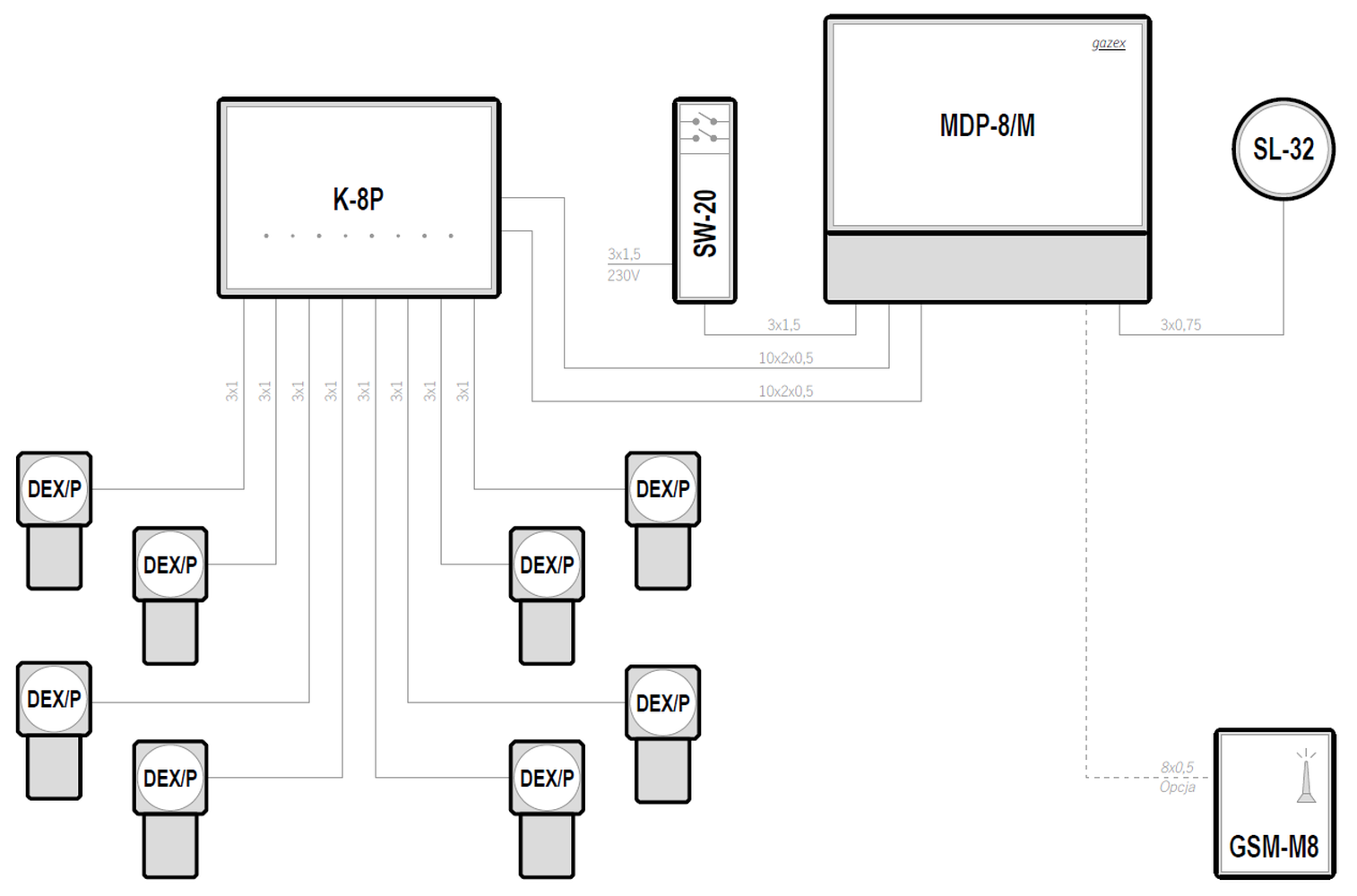
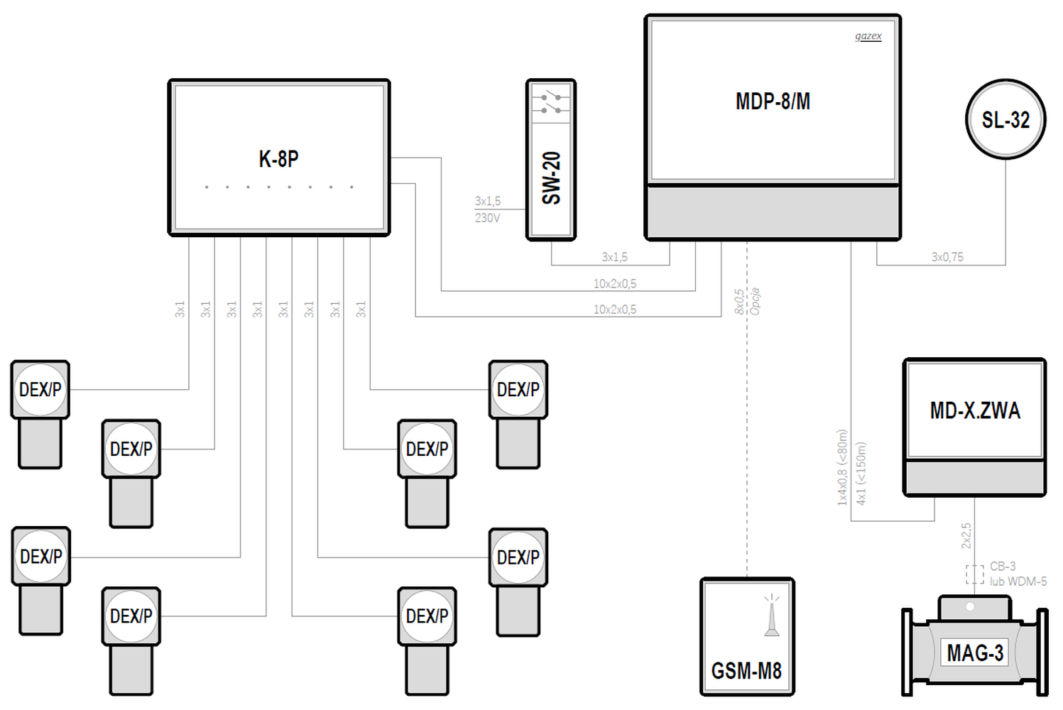
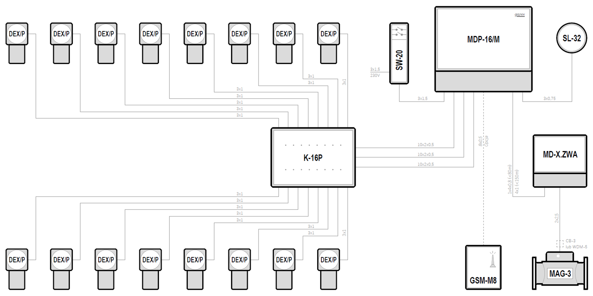
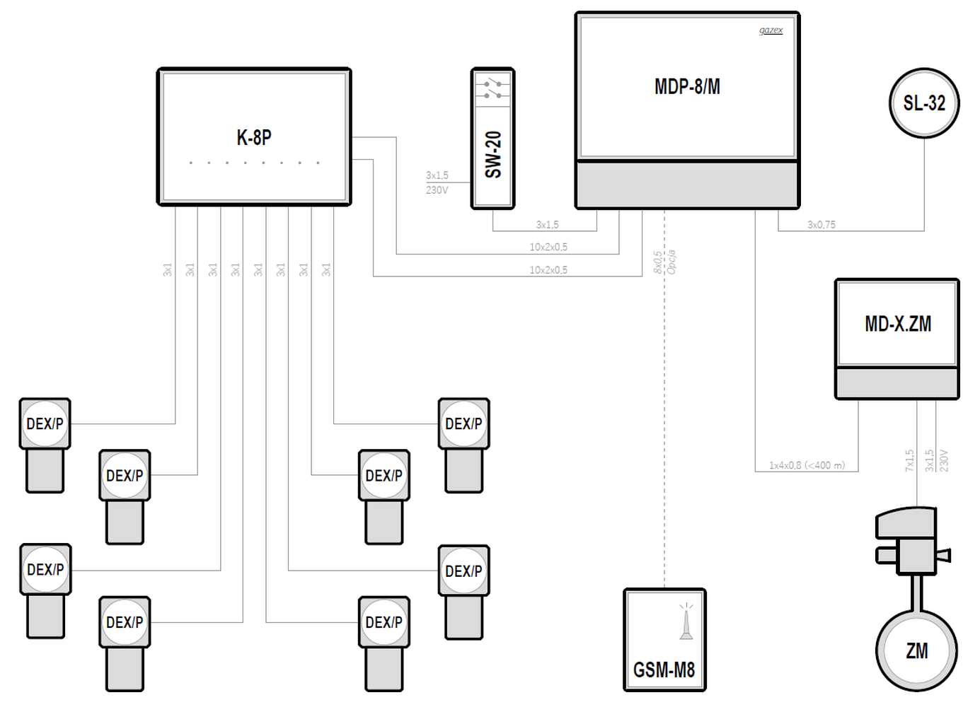
| 230VAC | MDP-16/M | 16 | DEX/P | — | Preview PDF DWG |
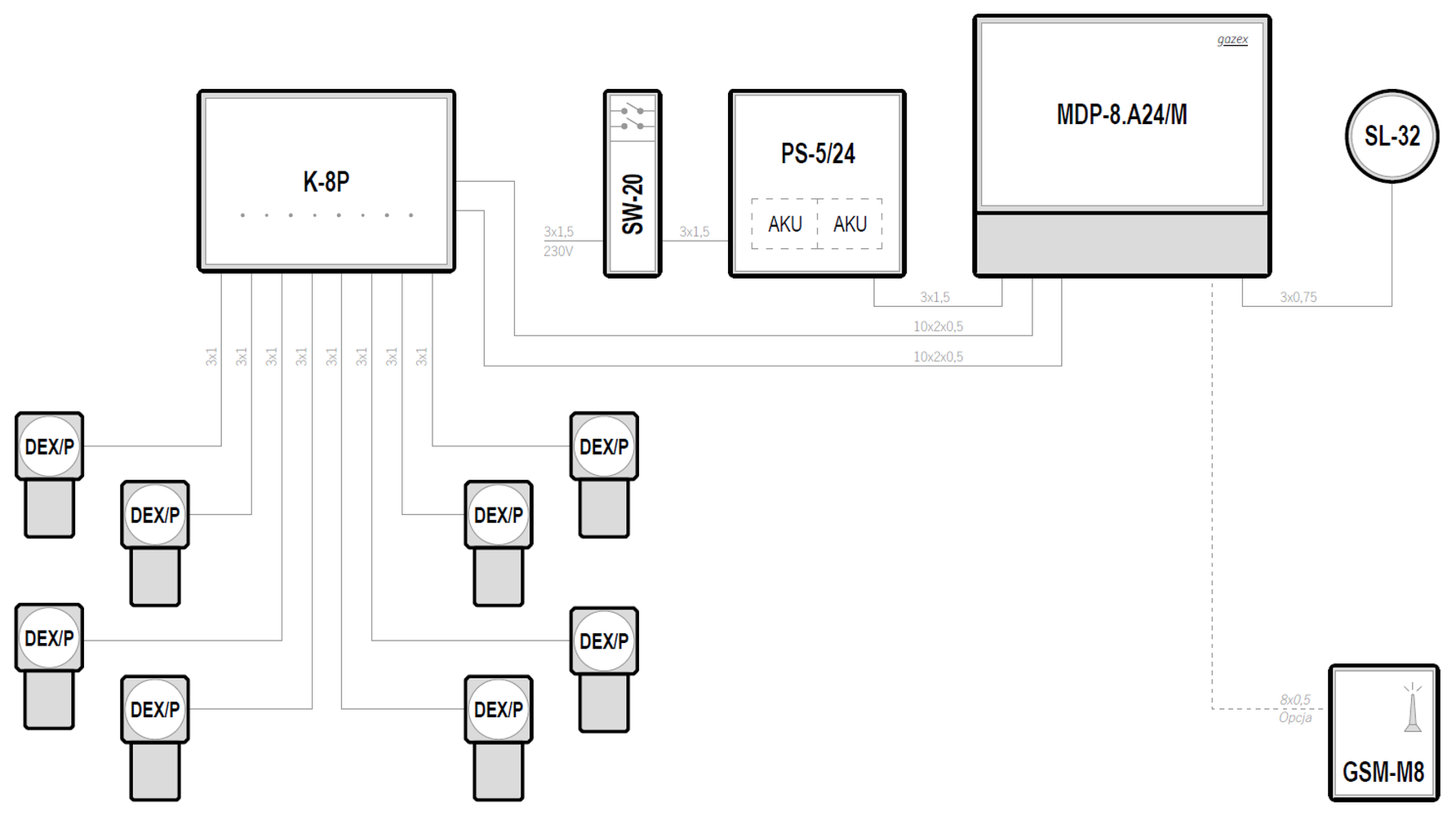
| 24VDC | MDP-16.A24/M | 16 | DEX/P | ✓ | Preview PDF DWG |
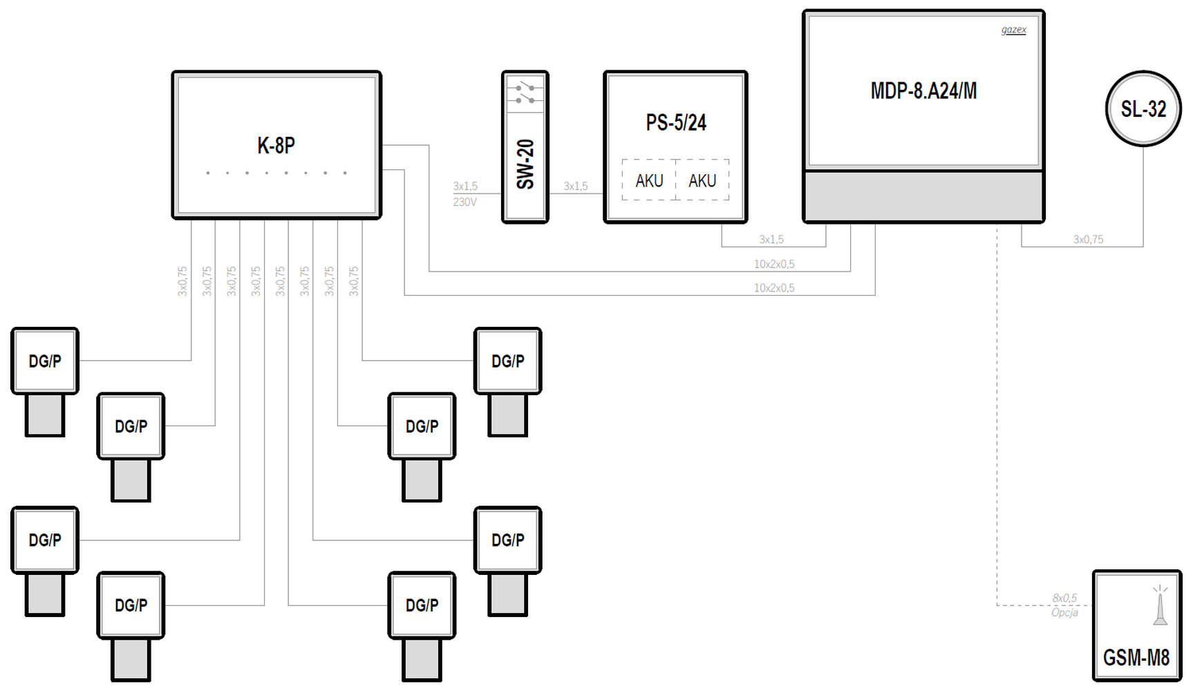
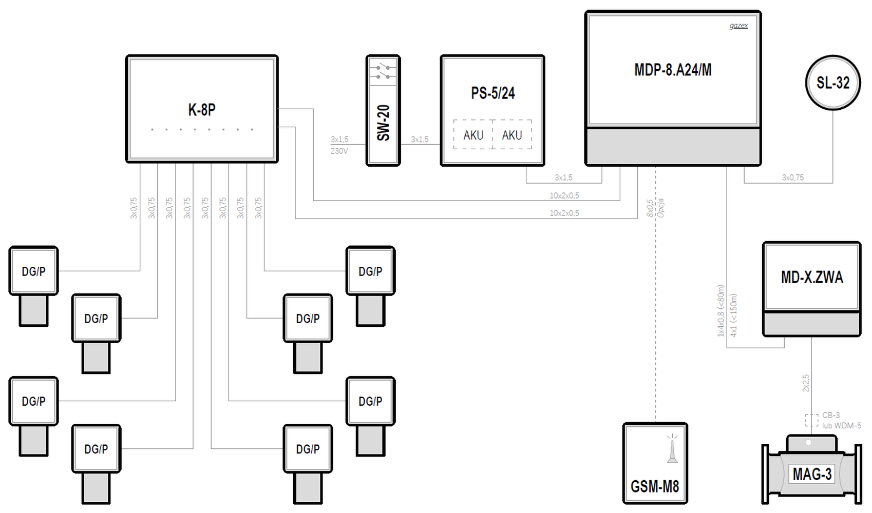
| 24VDC | MDP-16.A24/M | 16 | DG/P | ✓ | Preview PDF DWG |
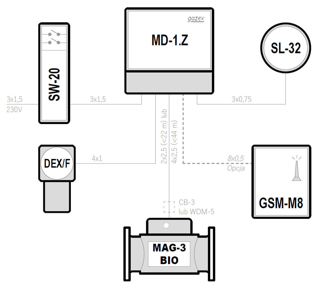
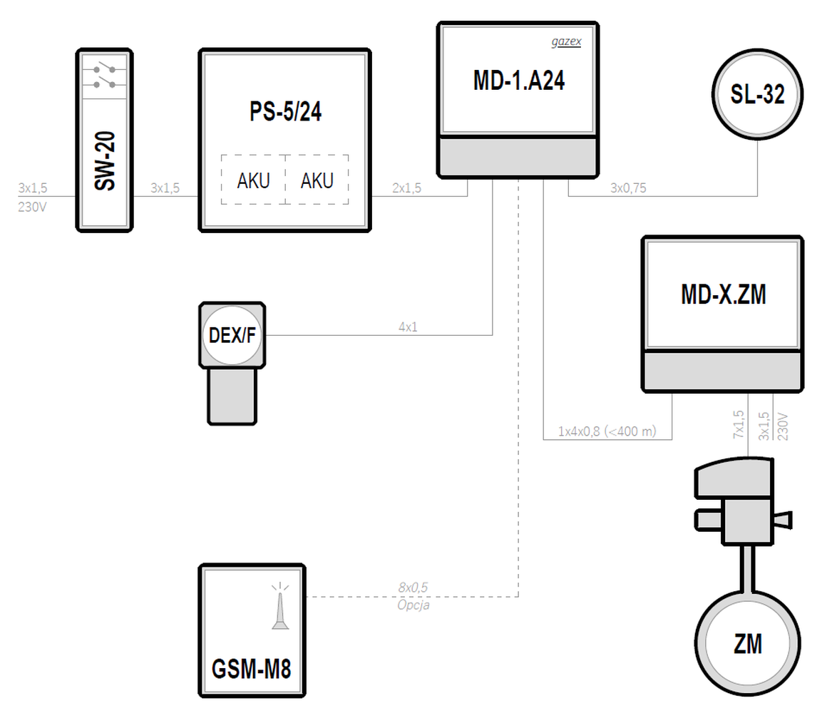
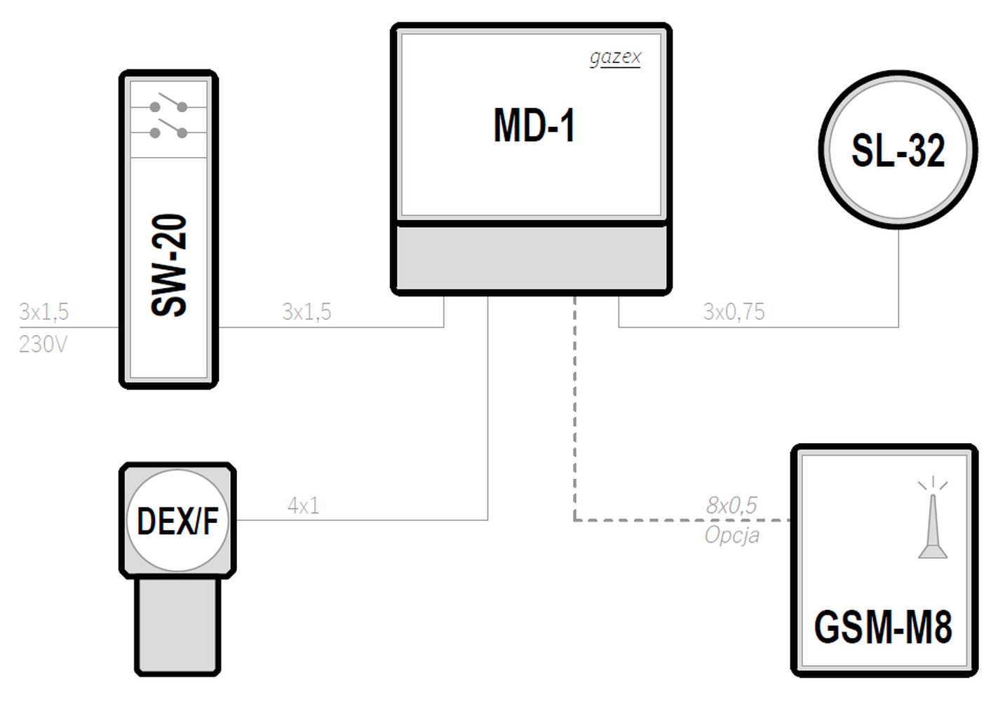
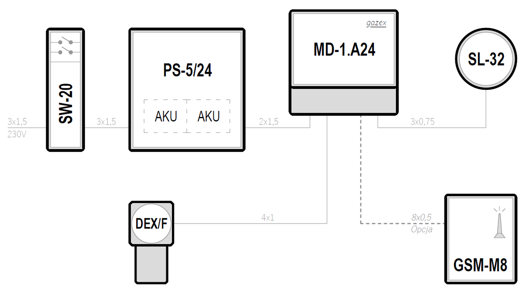
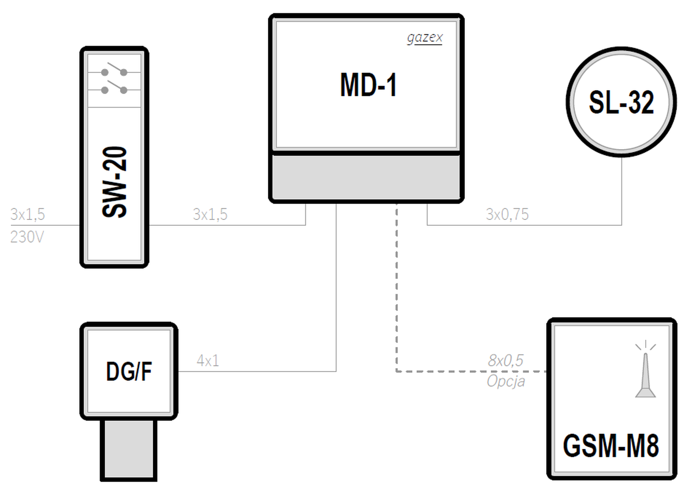
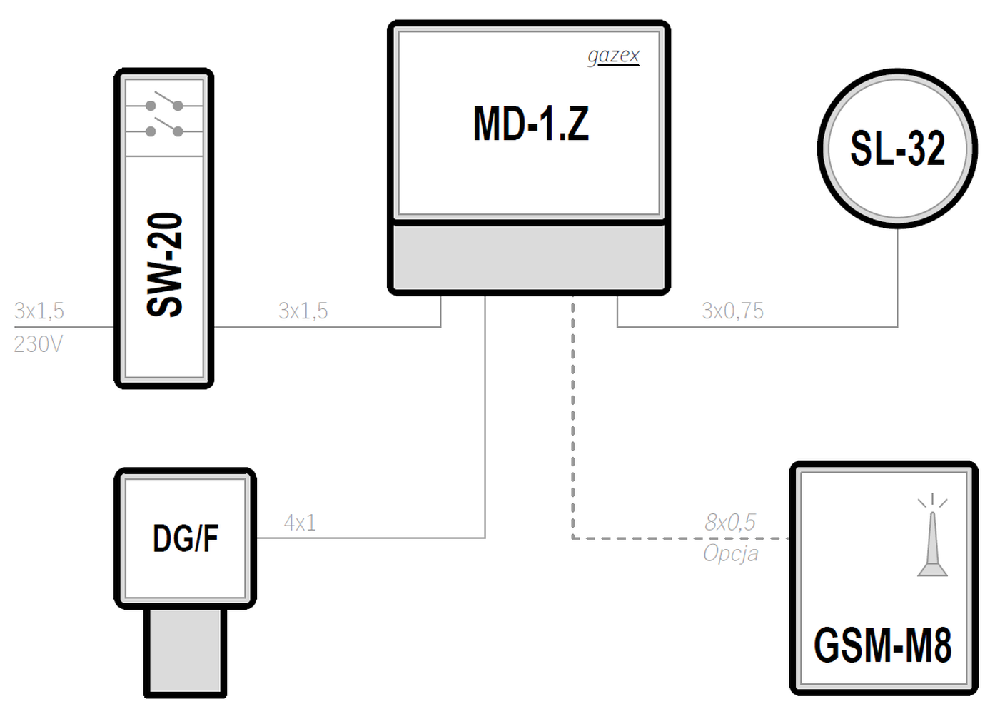
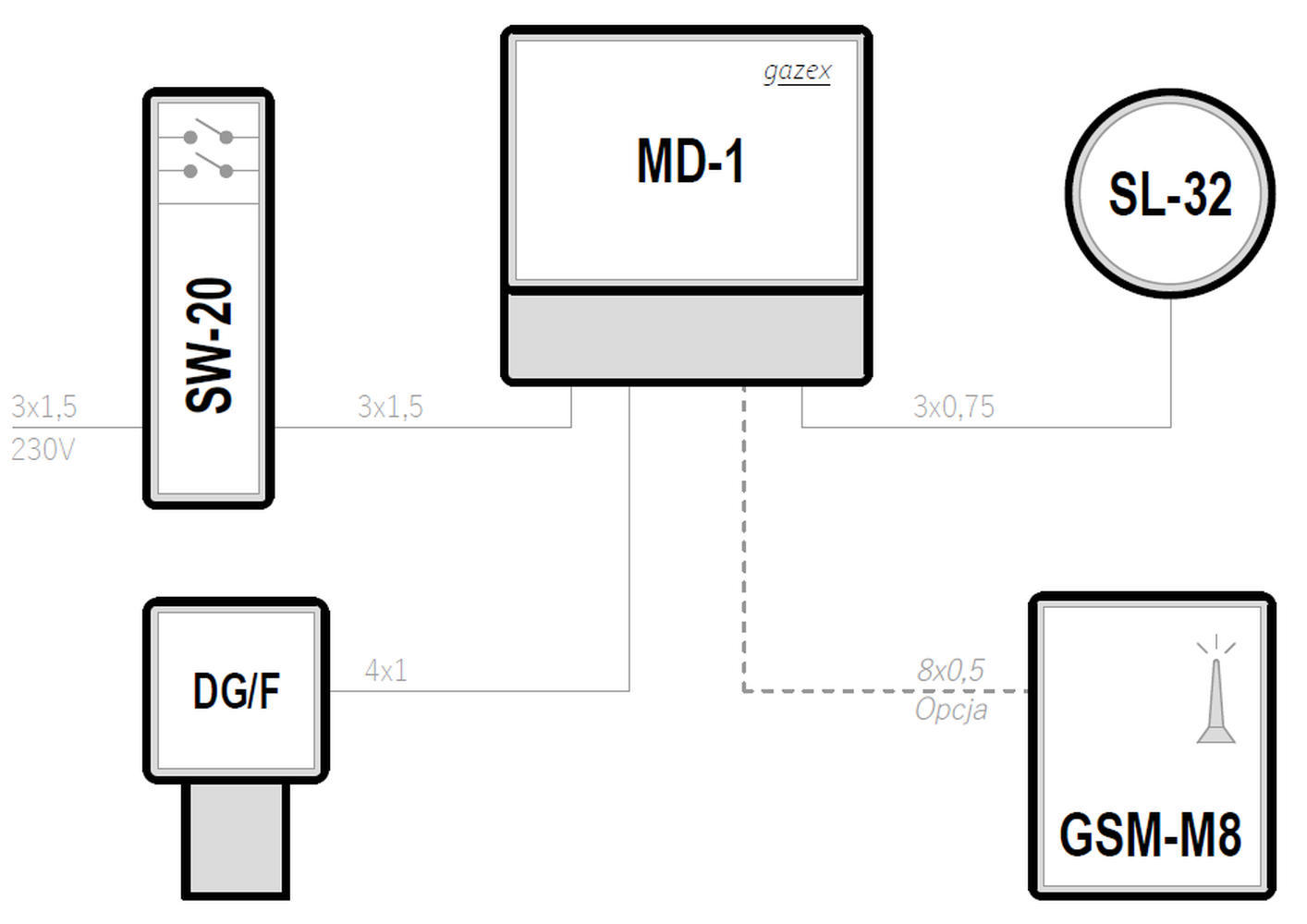
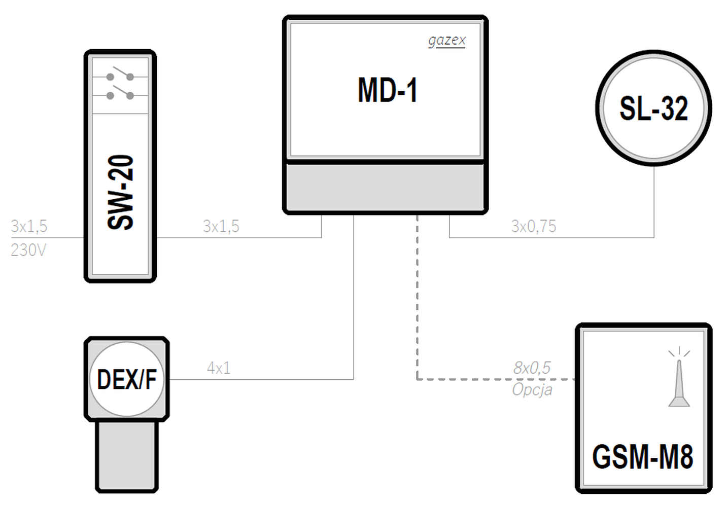
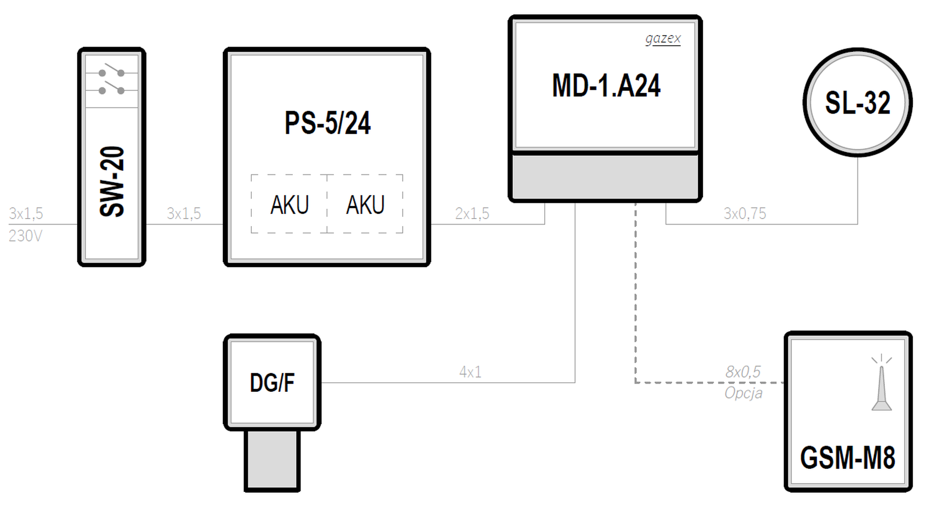
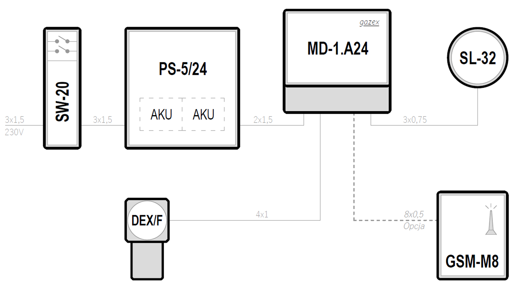
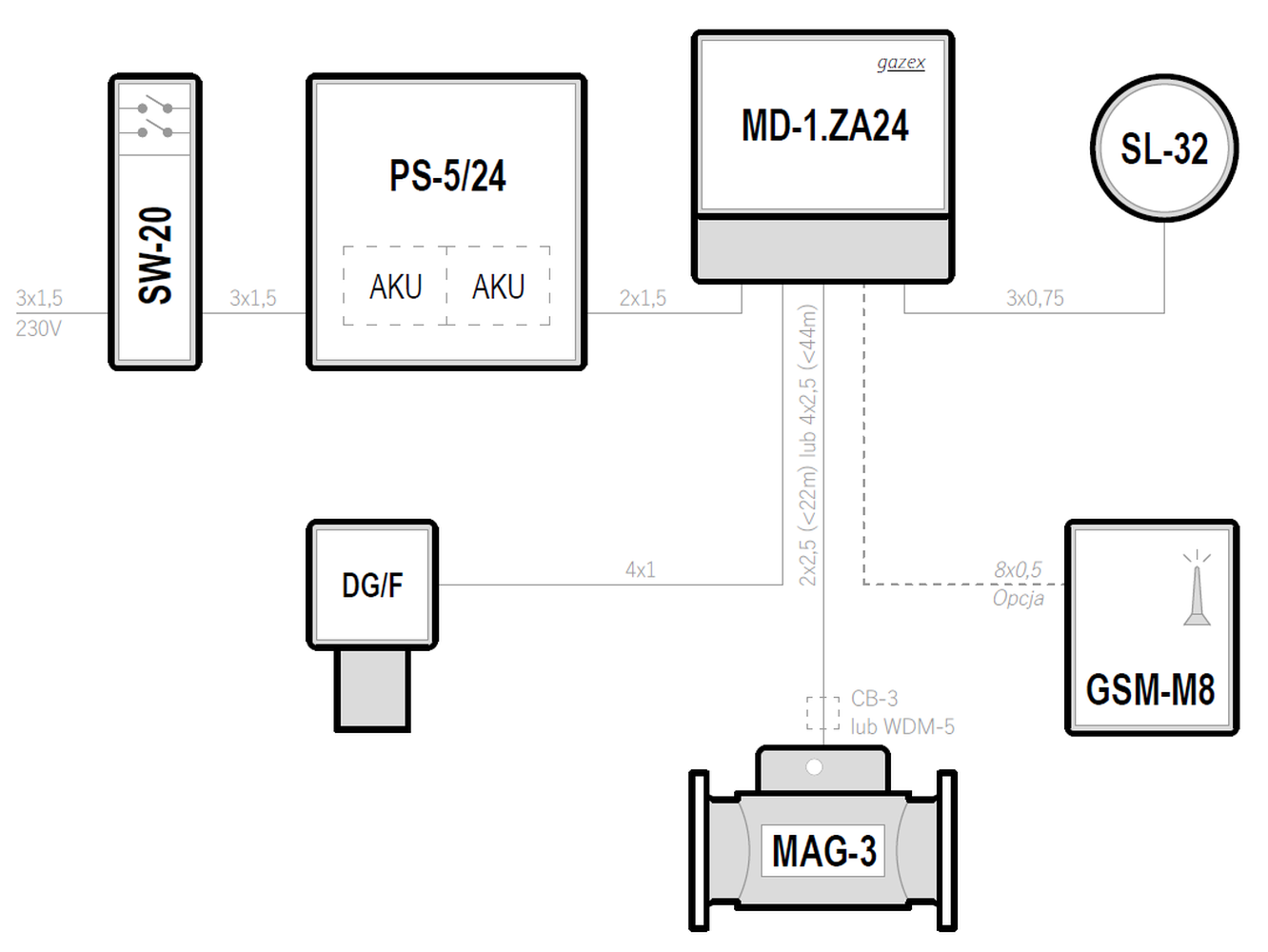
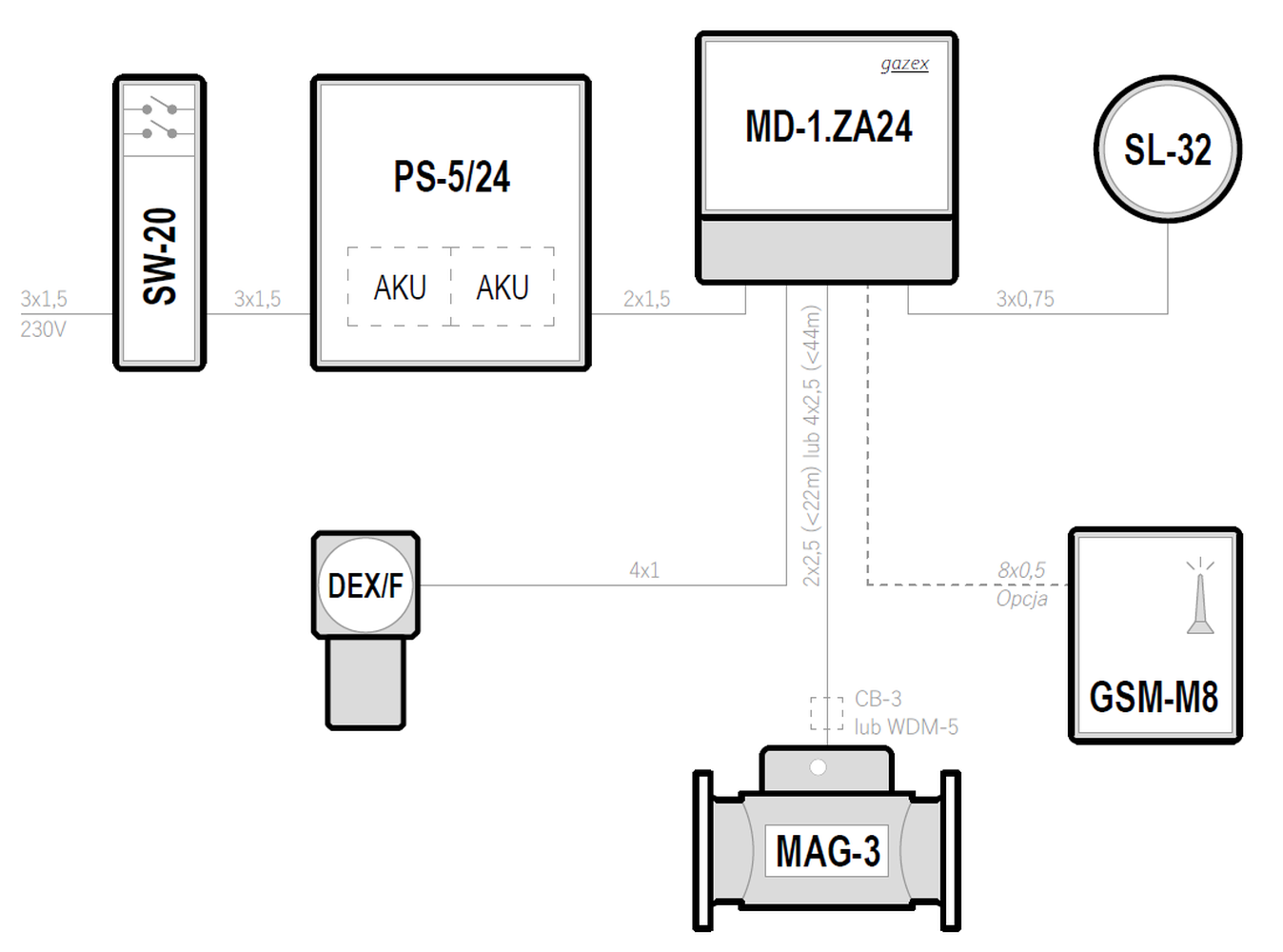
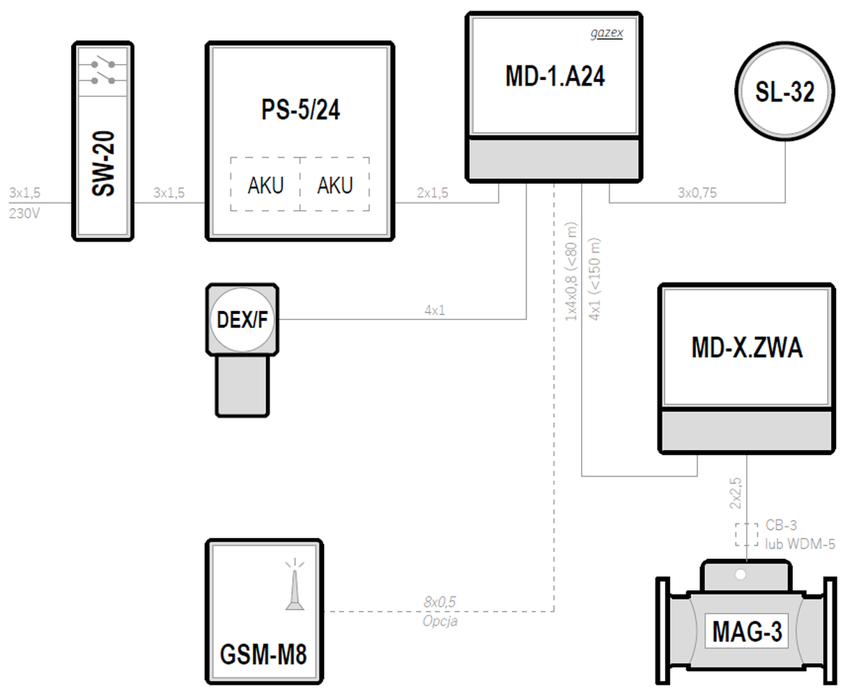
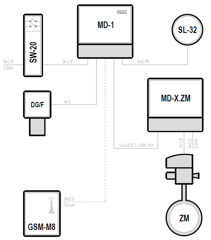
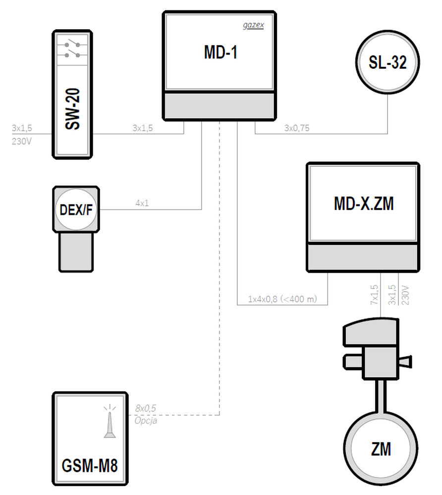
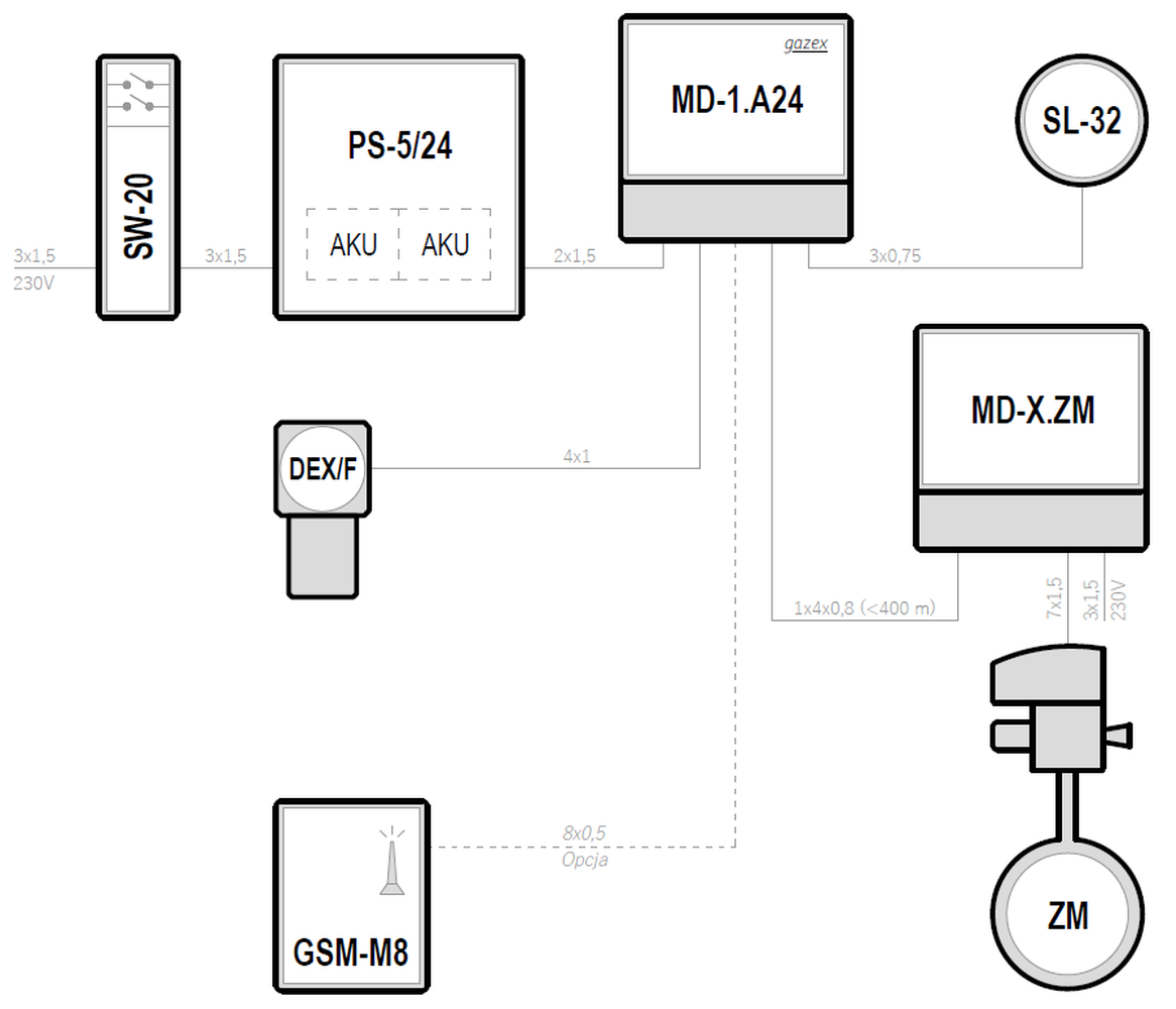
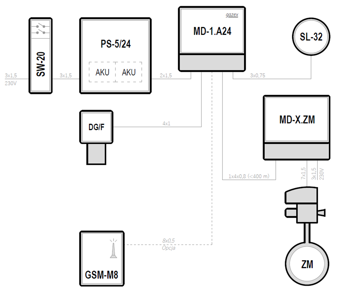
Systemy w oparciu o moduły sterujące typu MD-1
| Supply voltage | Control unit | Maximum number of gas detectors | Types of gas detectors | Emergency power backup | |
|---|---|---|---|---|---|
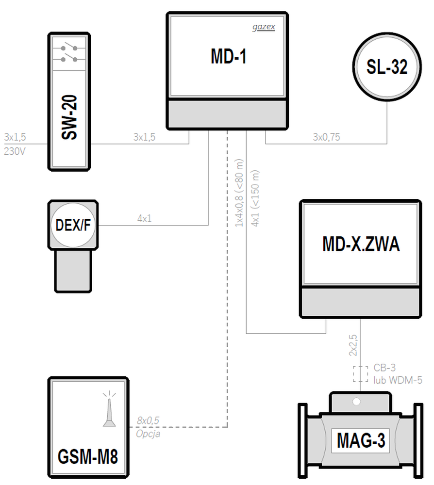
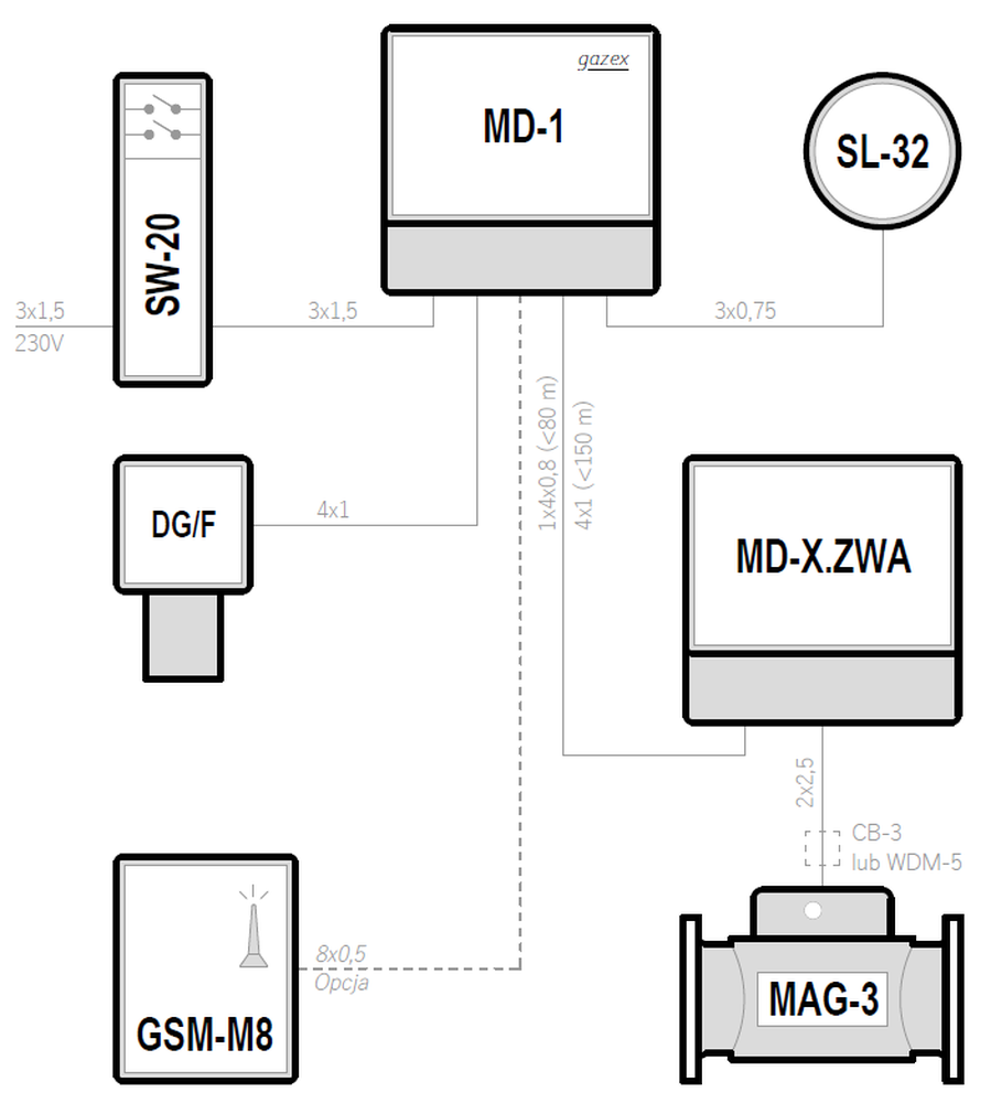
| 230VAC | MD-1 | 1 | DG/F | — | Preview PDF DWG |
| 230VAC | MD-1 | 1 | DEX/F | — | Preview PDF DWG |
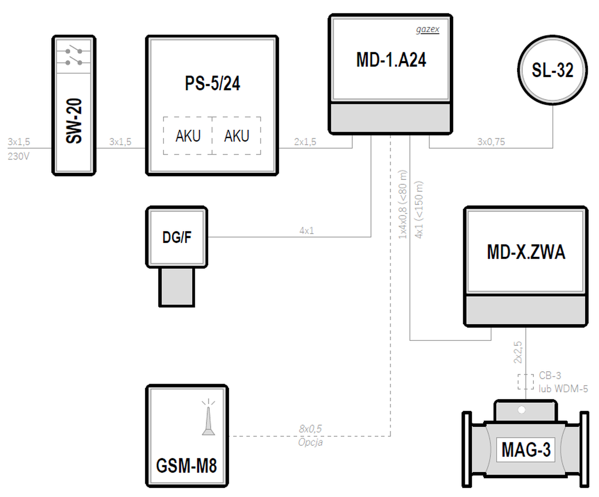
| 24VDC | MD-1.A24 | 1 | DG/F | ✓ | Preview PDF DWG |
| 24VDC | MD-1.A24 | 1 | DEX/F | ✓ | Preview PDF DWG |
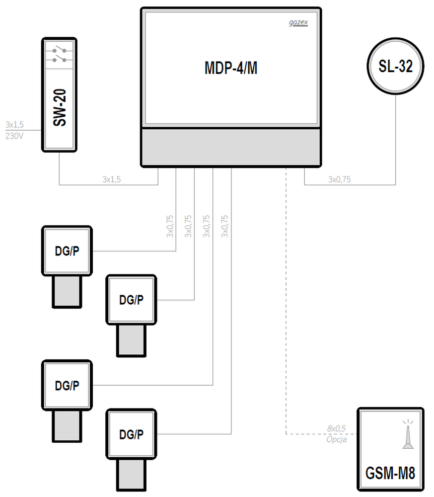
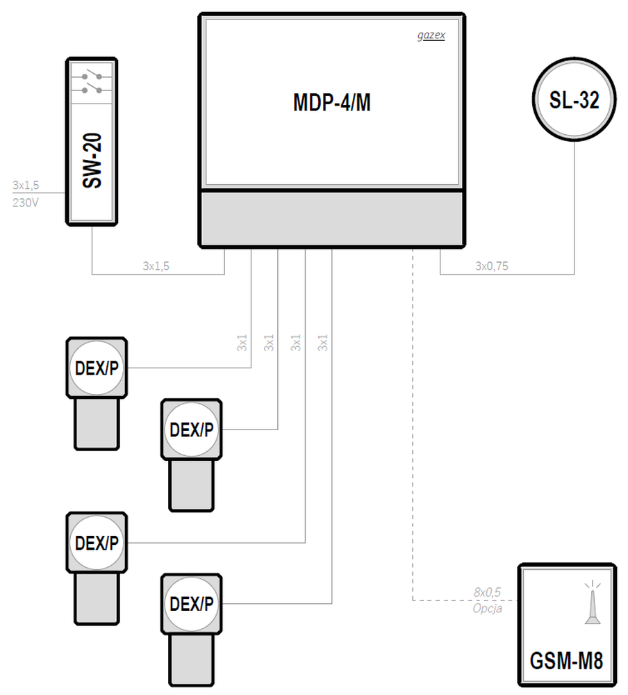
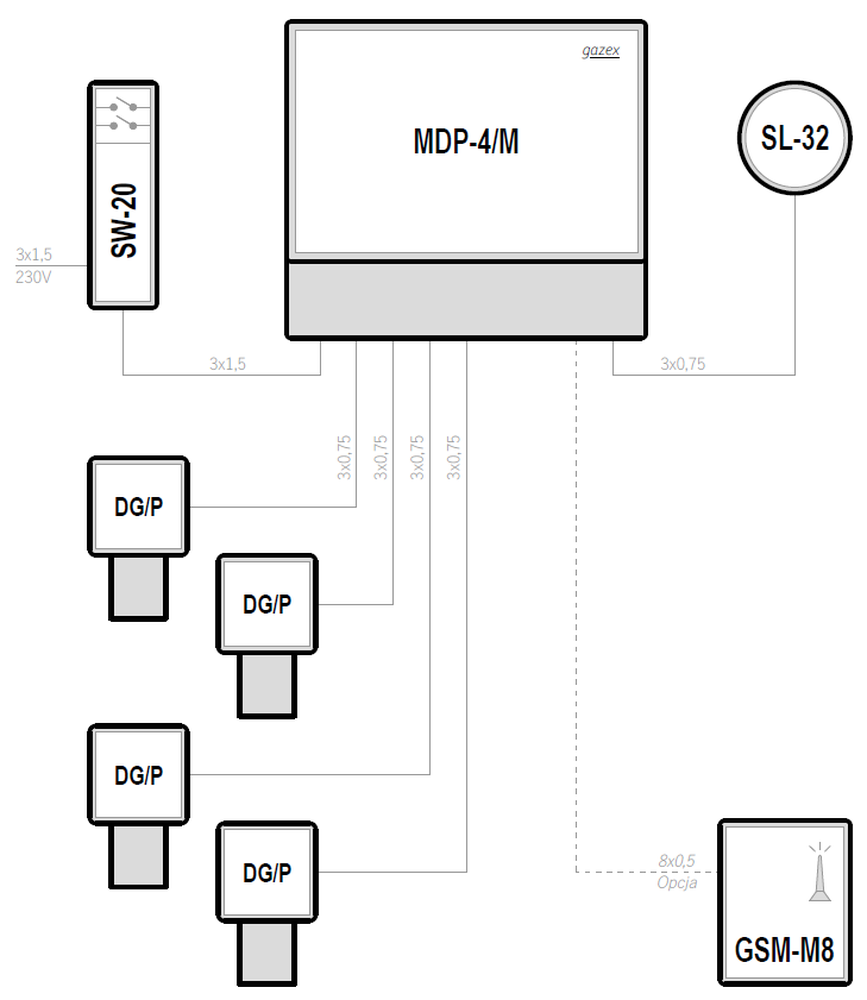
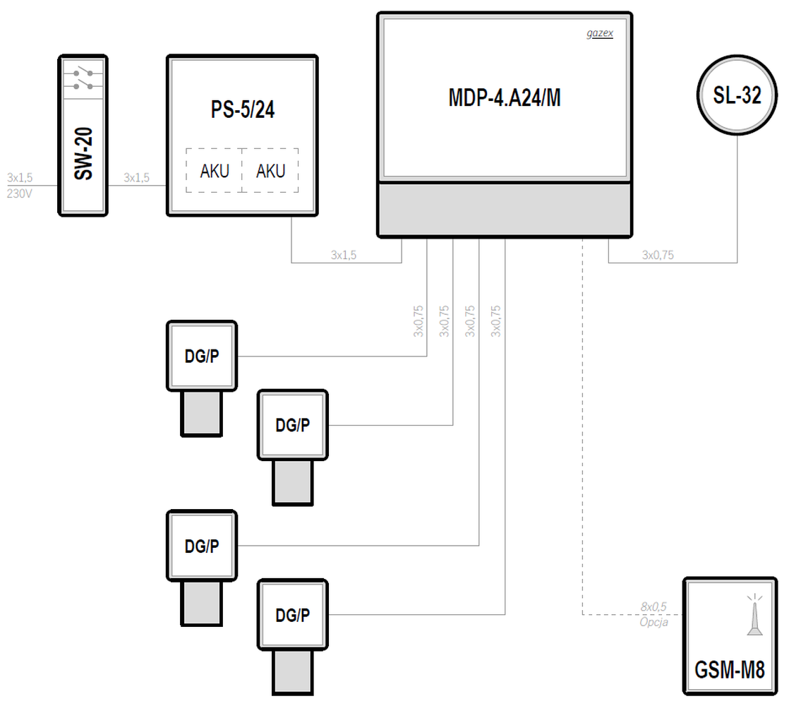
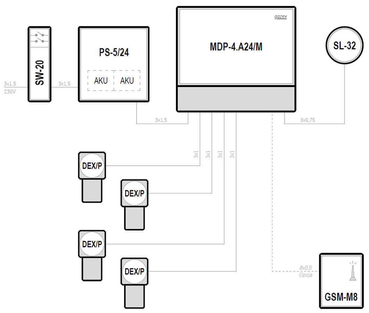
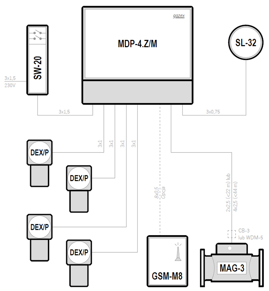
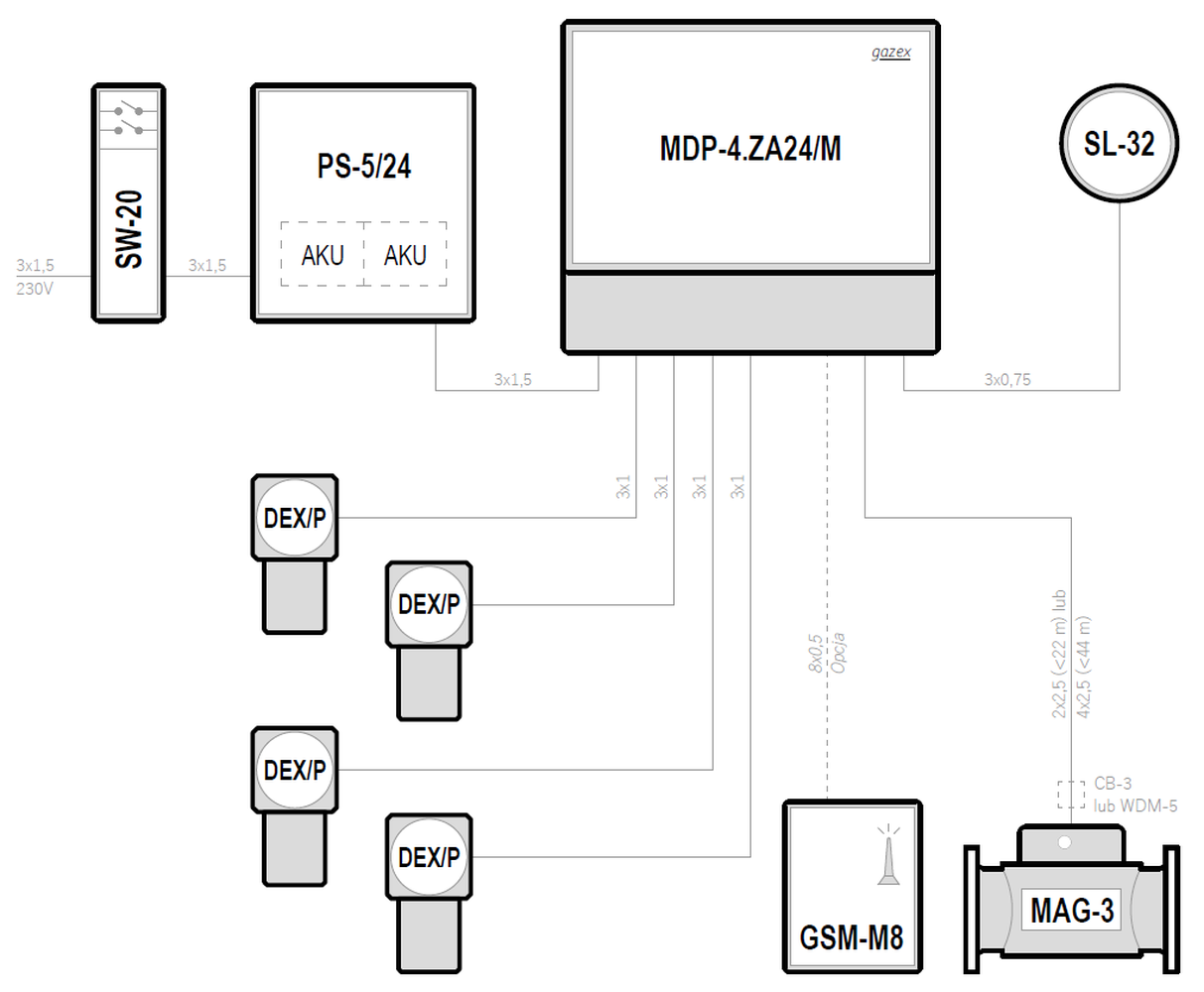
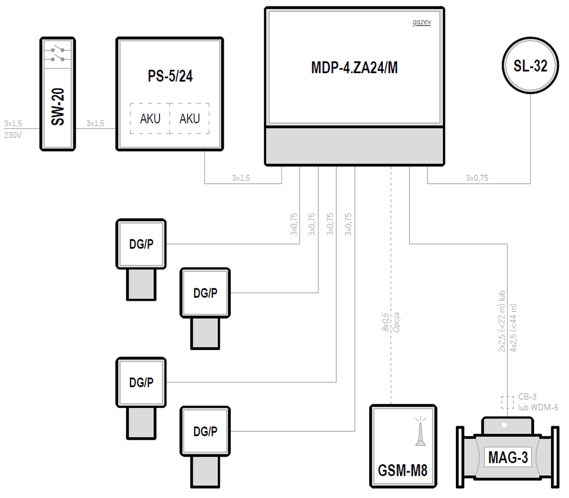
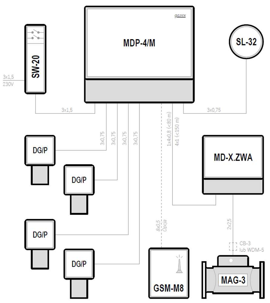
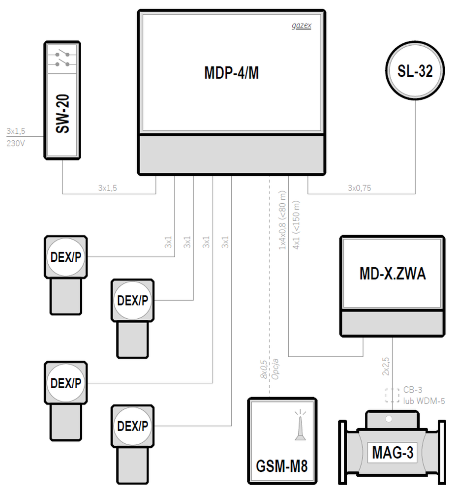
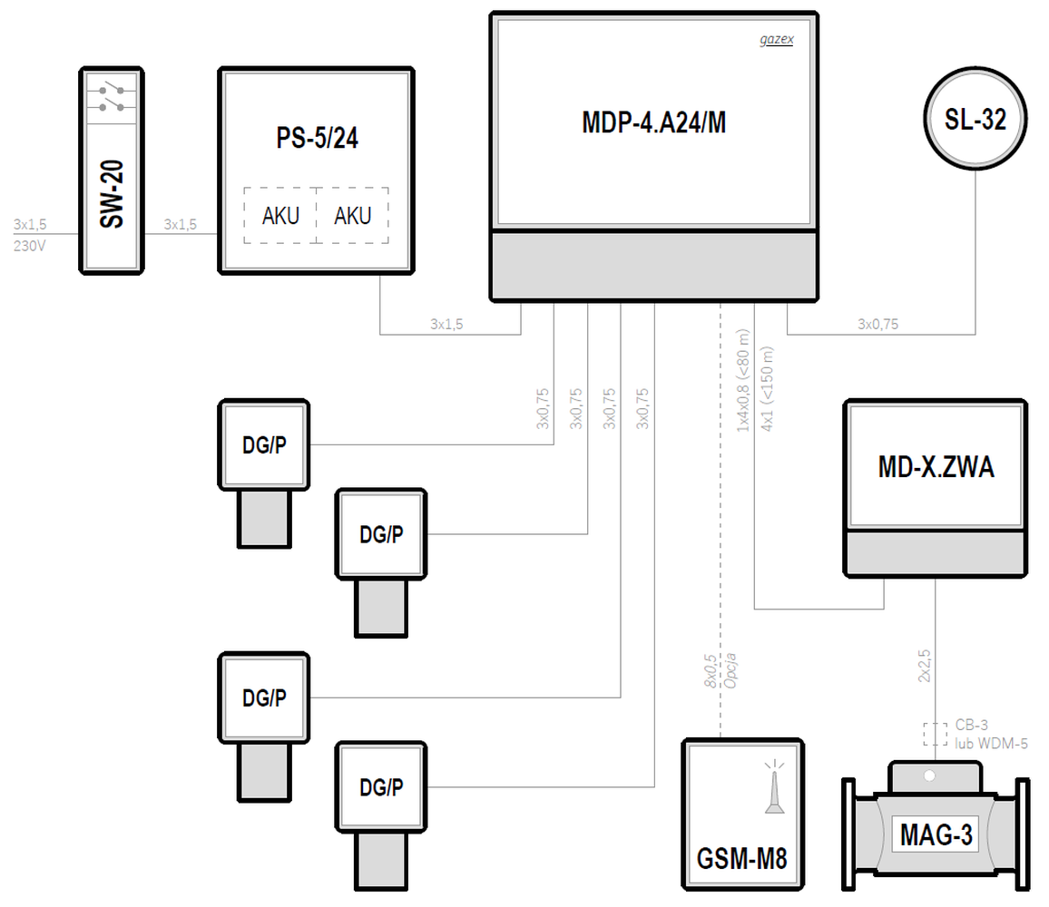
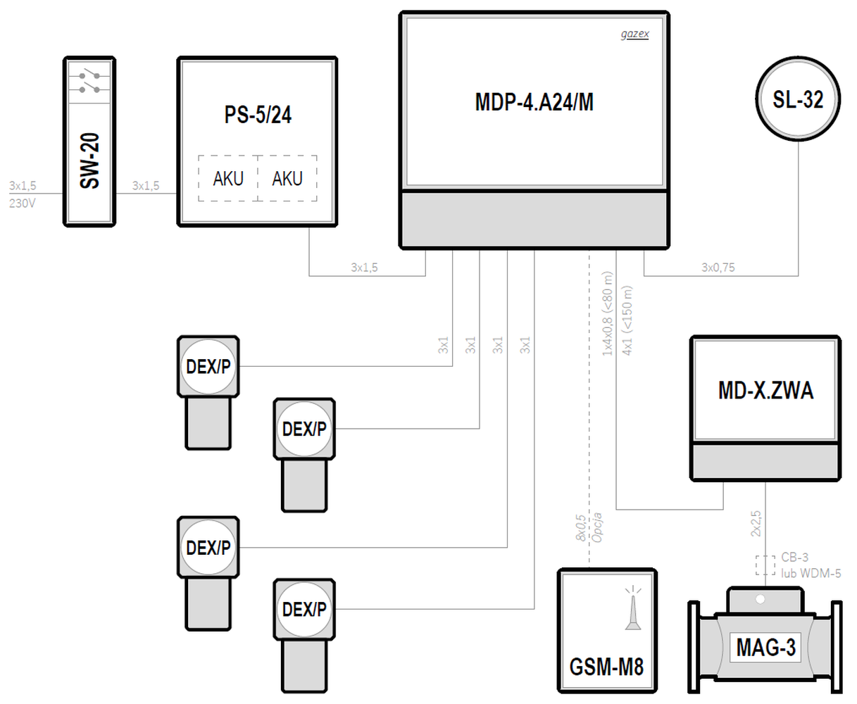
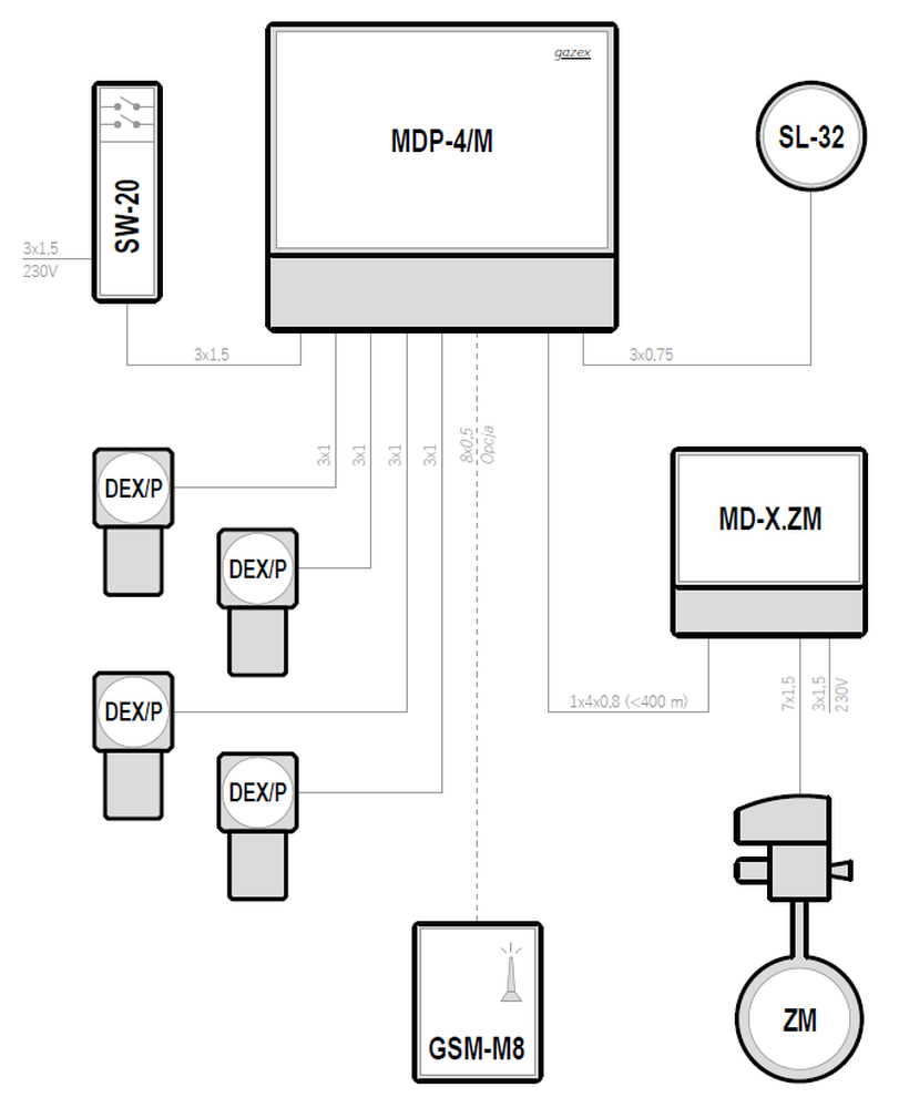
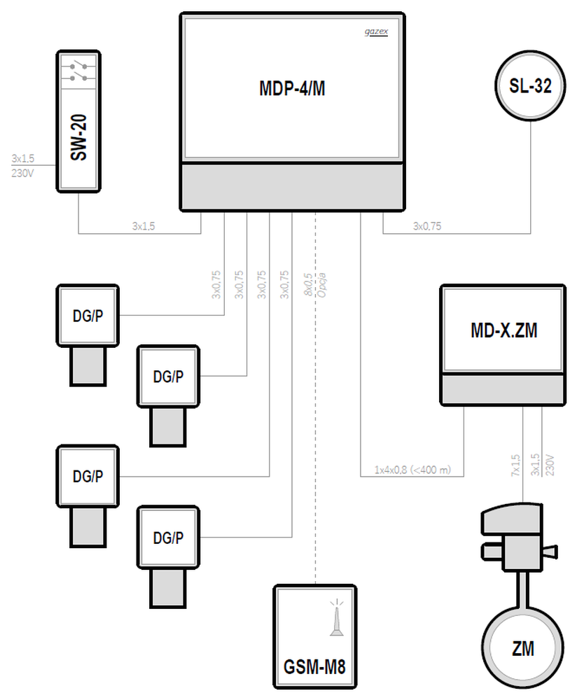
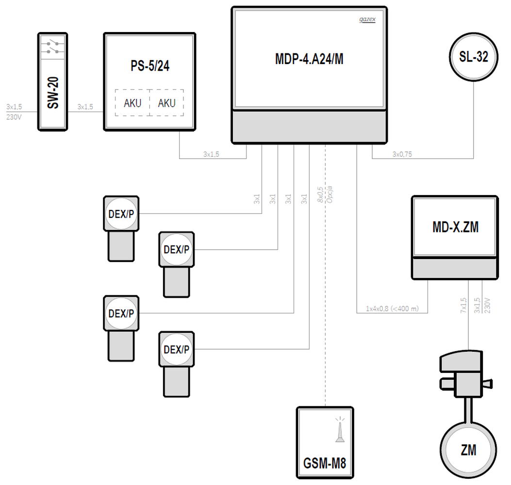
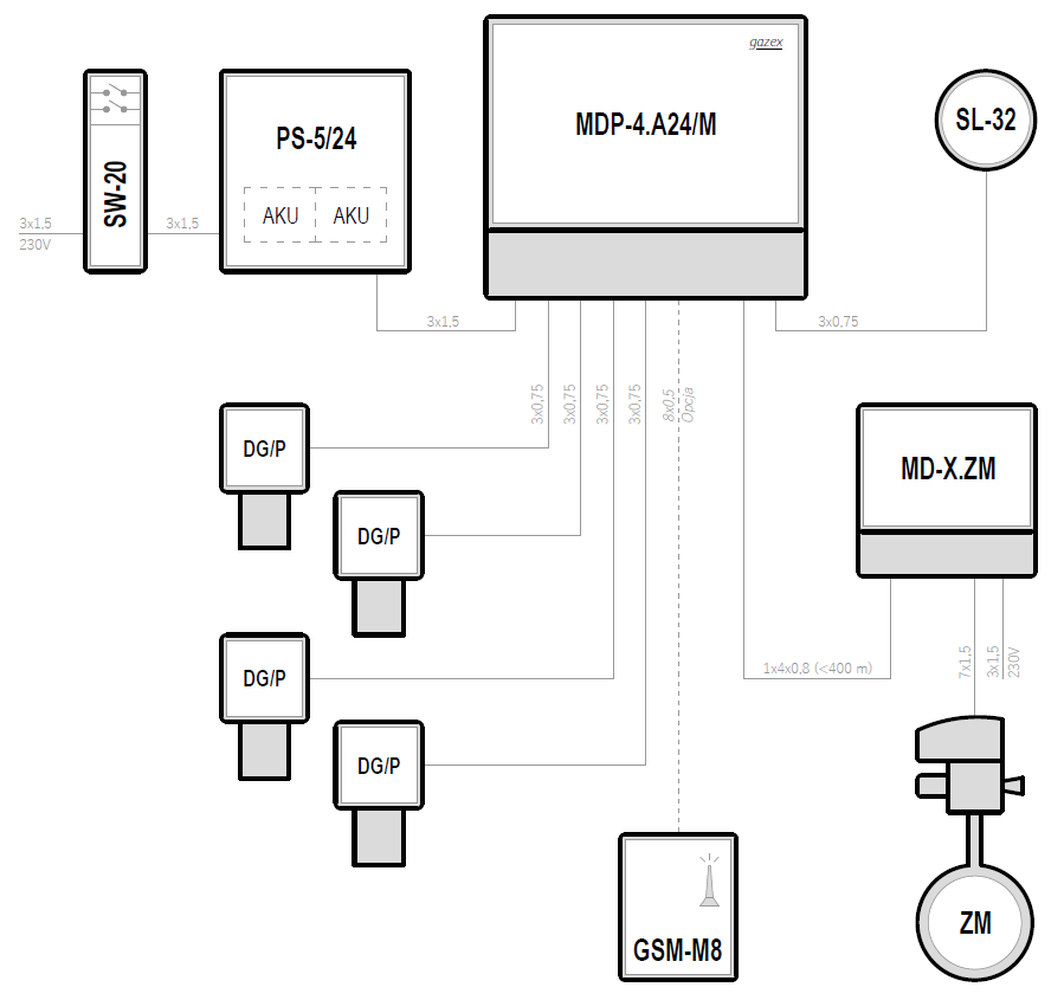
Systemy w oparciu o moduły sterujące typu MDP-4
| Supply voltage | Control unit | Maximum number of gas detectors | Types of gas detectors | Emergency power backup | |
|---|---|---|---|---|---|
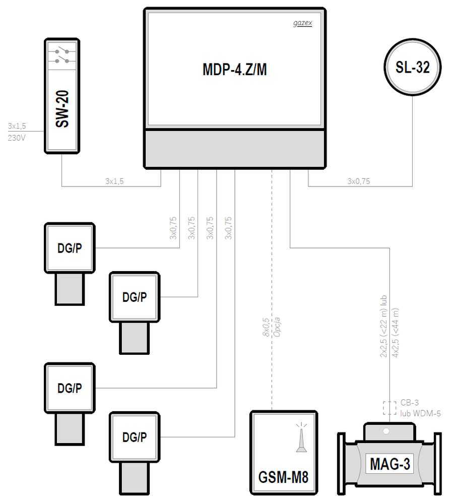
| 230VAC | MDP-4/M | 4 | DEX/P | — | Preview PDF DWG |
| 230VAC | MDP-4/M | 4 | DG/P | — | Preview PDF DWG |
| 24VDC | MDP-4.A24/M | 4 | DG/P | ✓ | Preview PDF DWG |
| 24VDC | MDP-4.A24/M | 4 | DEX/P | ✓ | Preview PDF DWG |
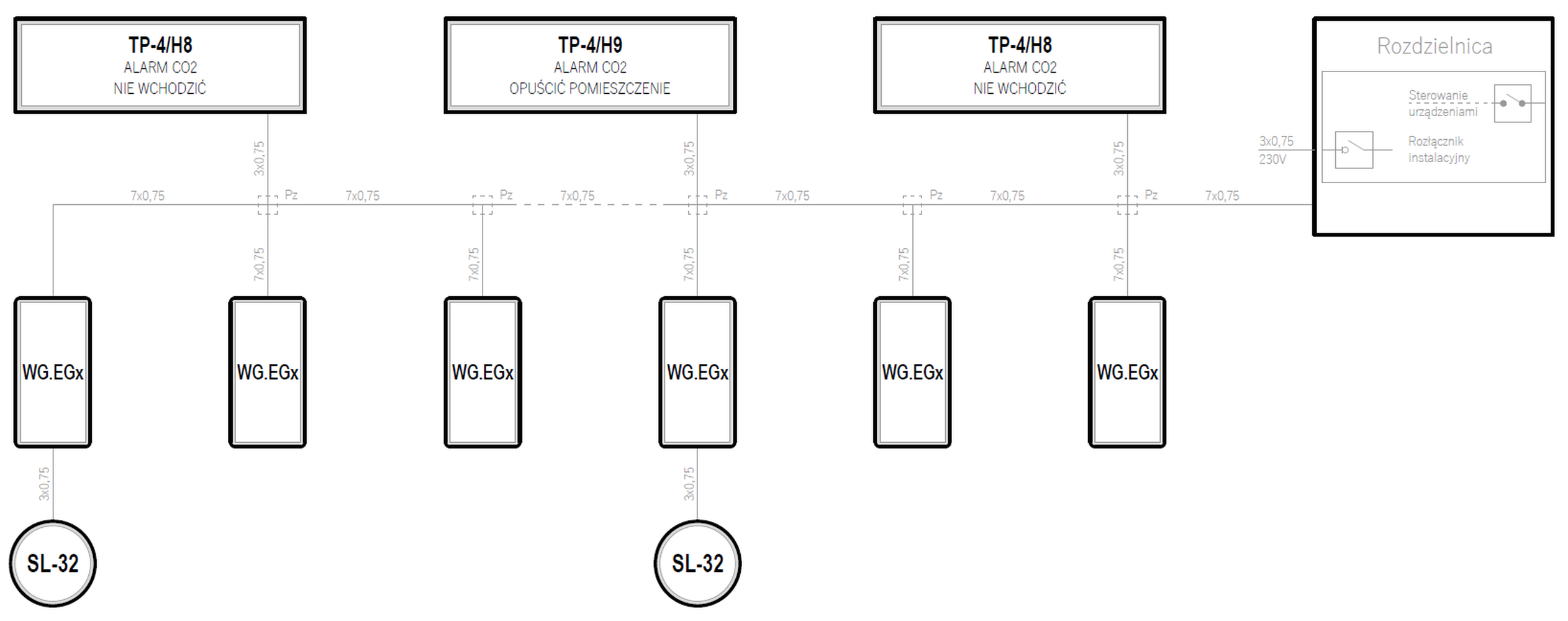
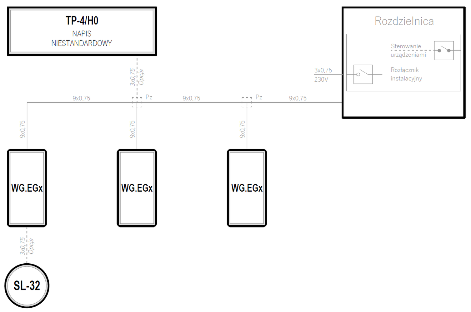
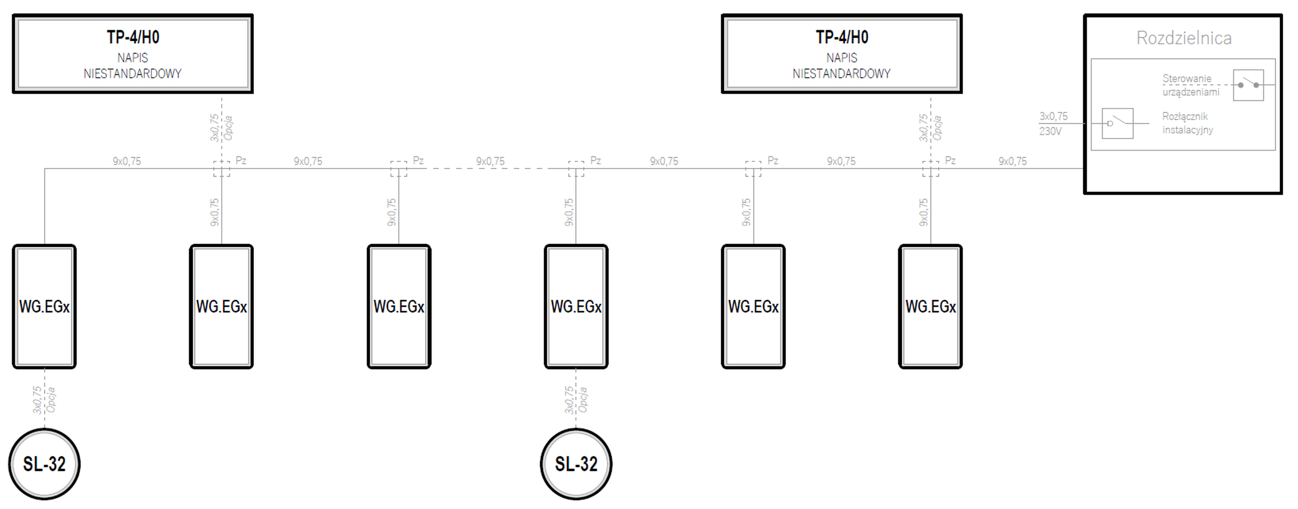
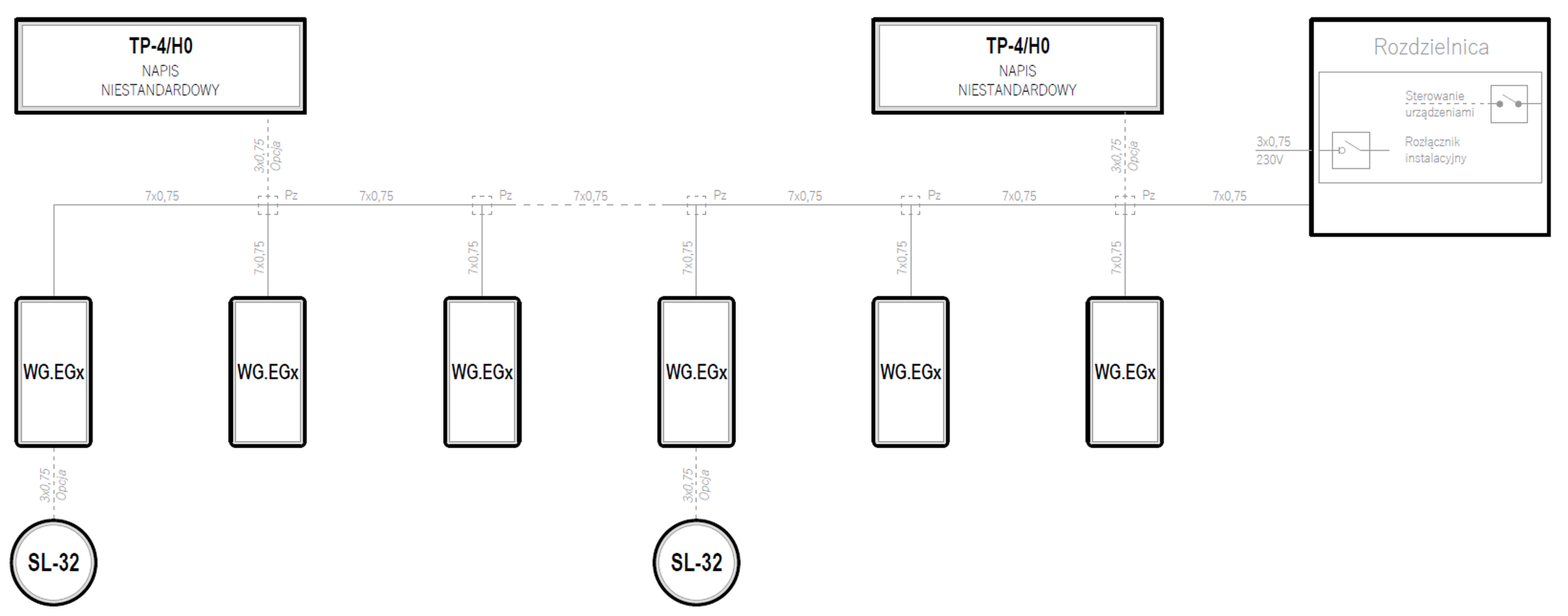
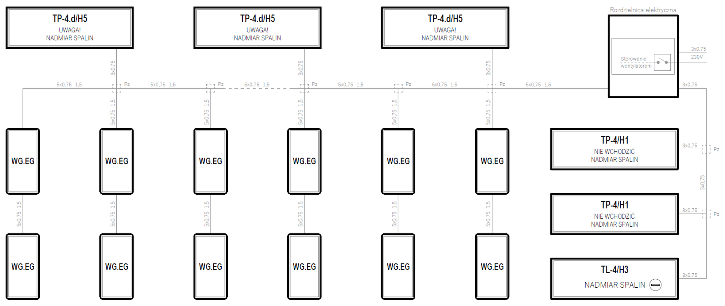
Systemy w oparciu o detektory typu WG.EGx
| Supply voltage | Control unit | Maximum number of gas detectors | Types of gas detectors | Emergency power backup | |
|---|---|---|---|---|---|
| 230VAC | — | ∞ | WG.EGx | — | Preview PDF DWG |
| 230VAC | — | ∞ | WG.EGx | — | Preview PDF DWG |
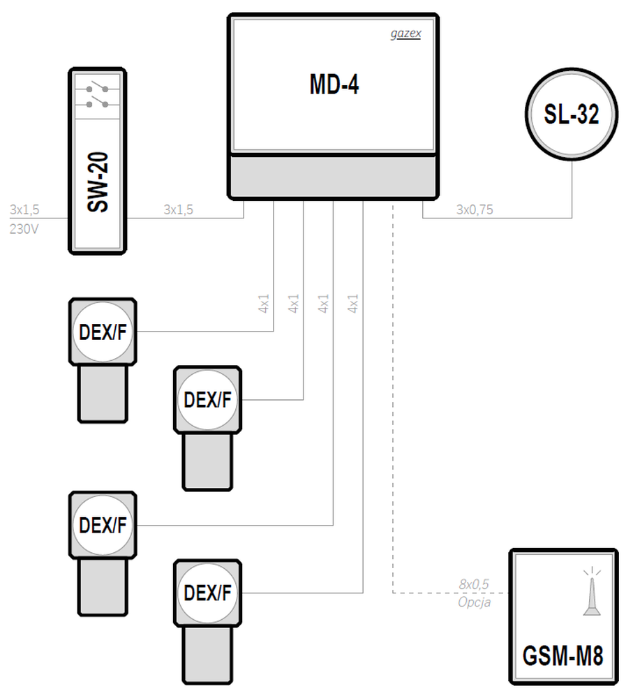
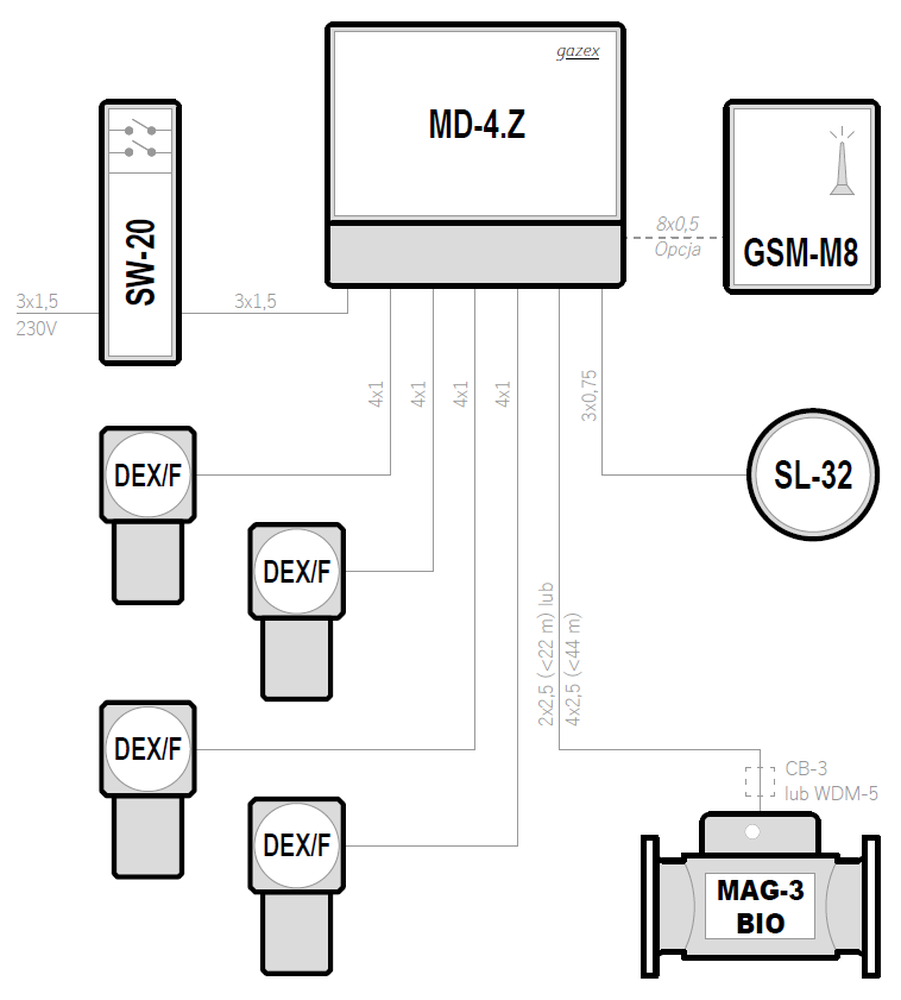
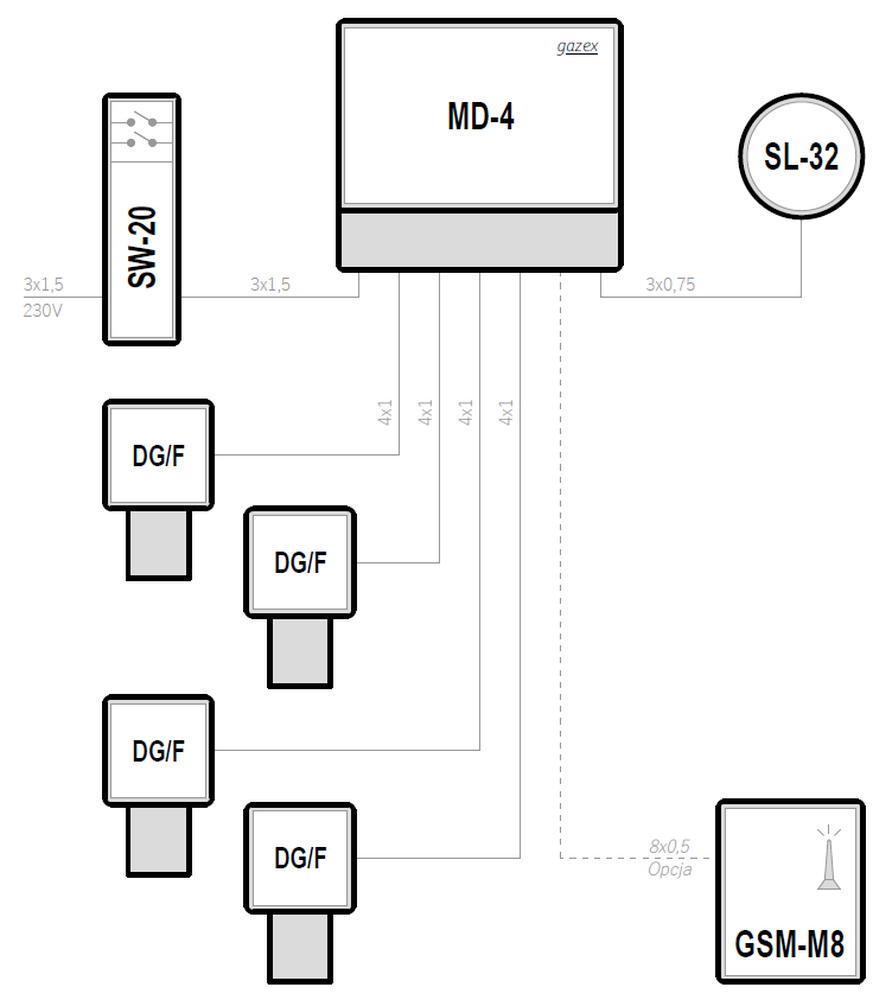
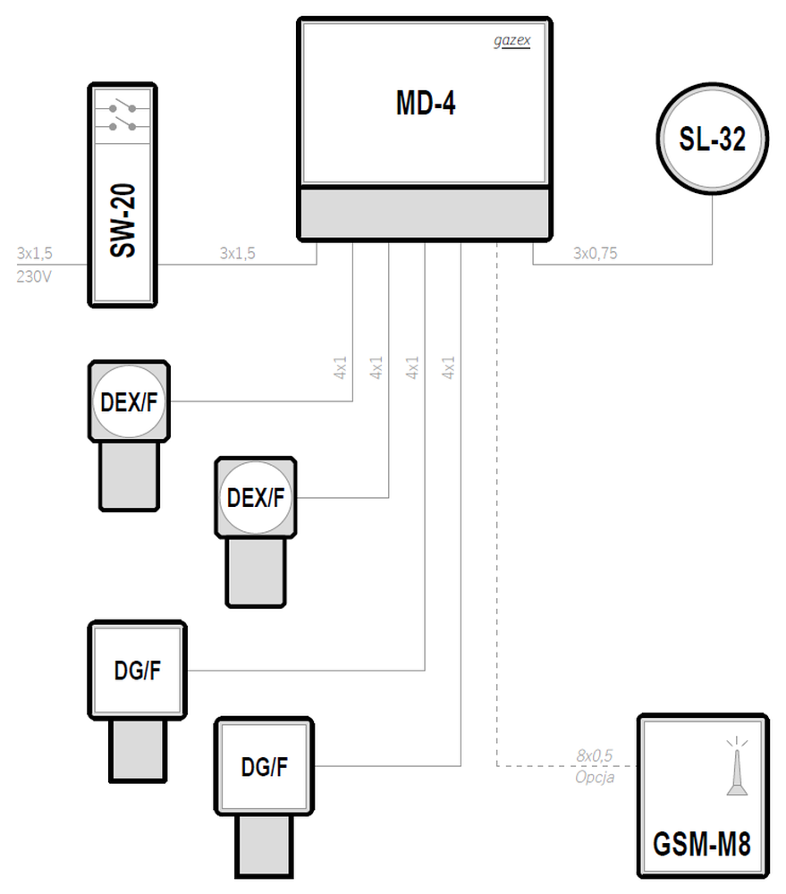
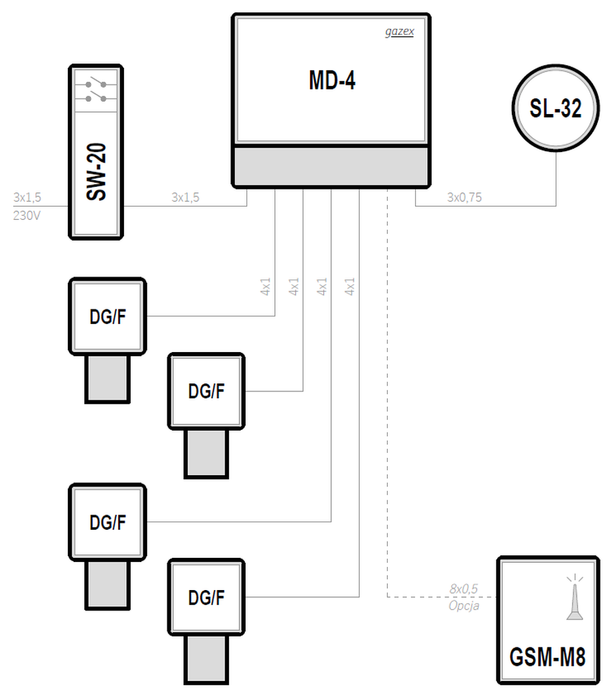
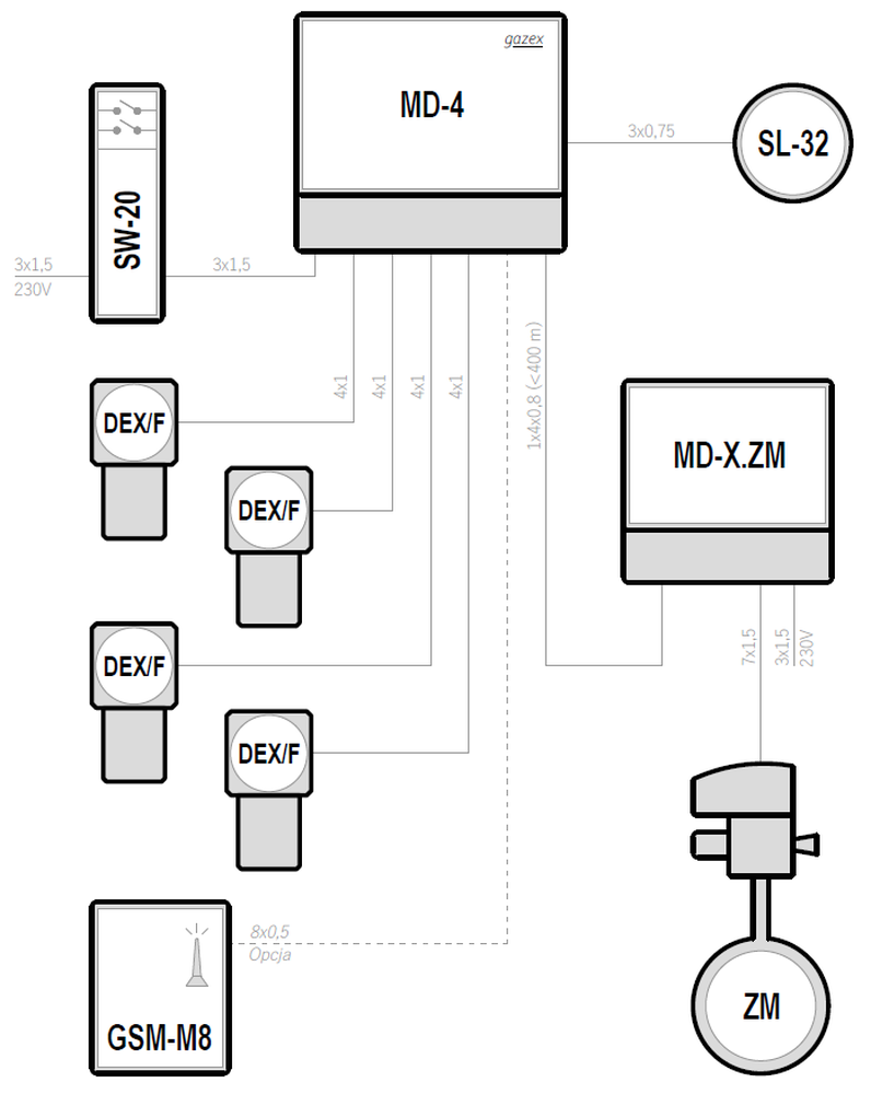
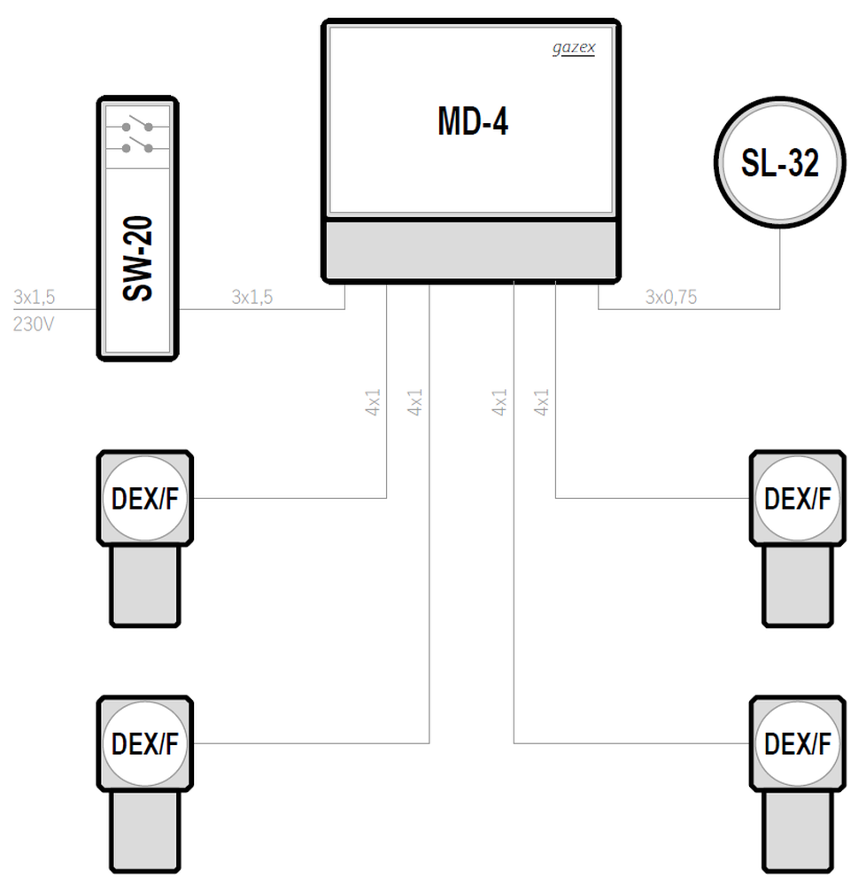
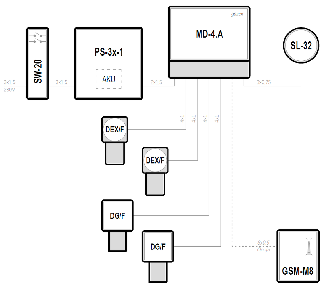
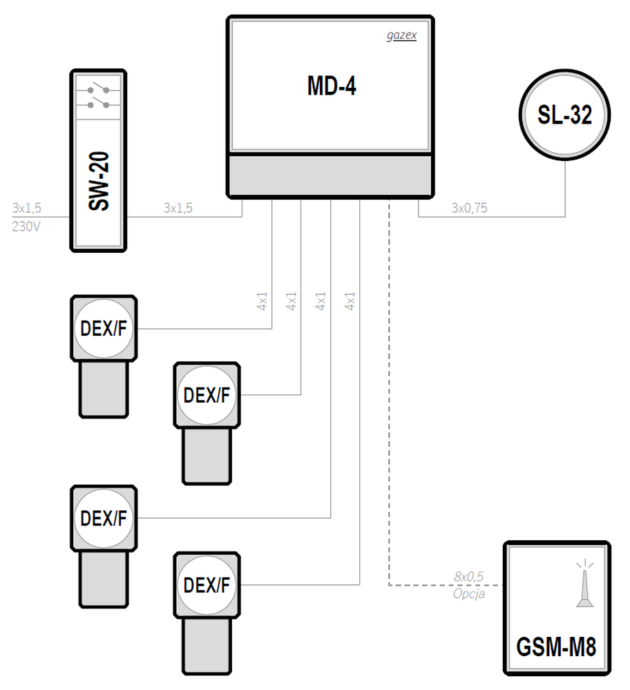
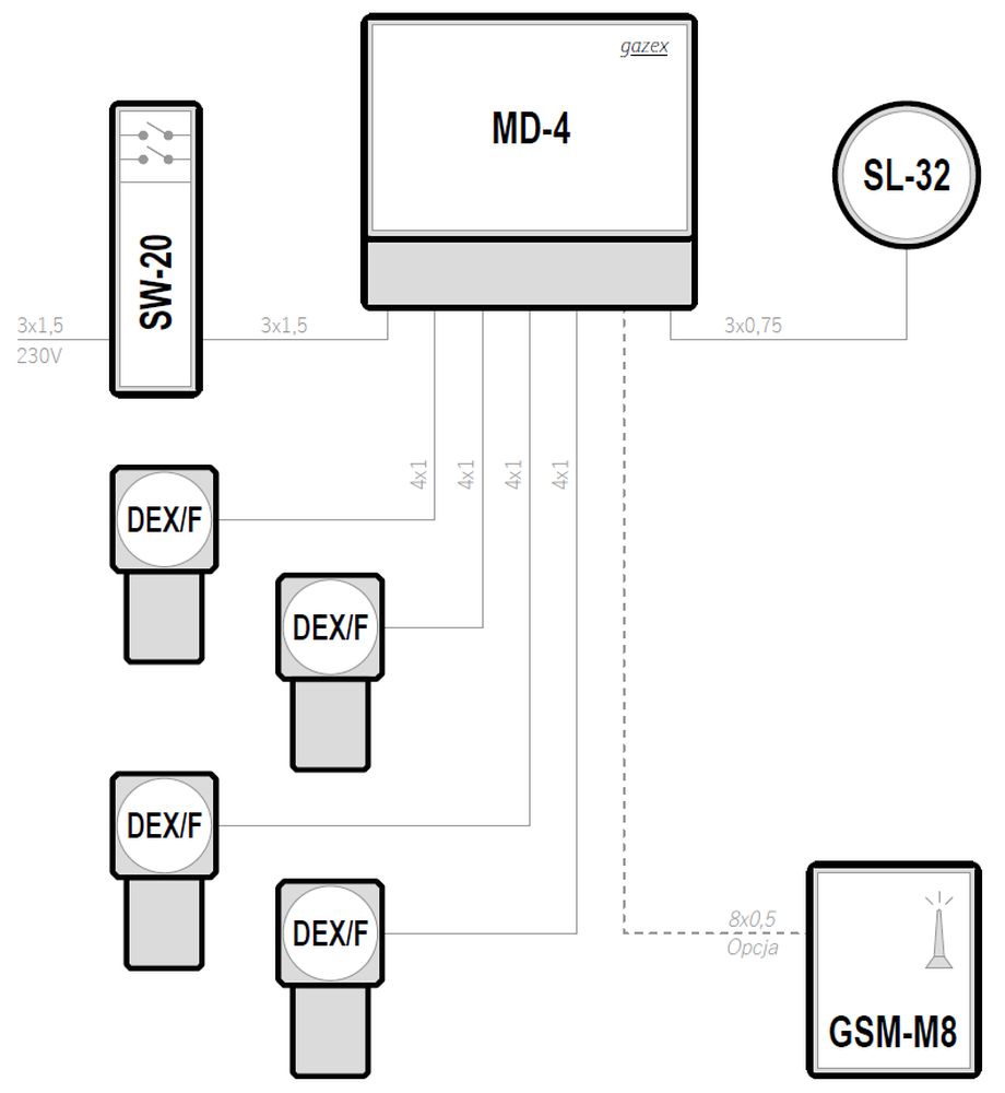
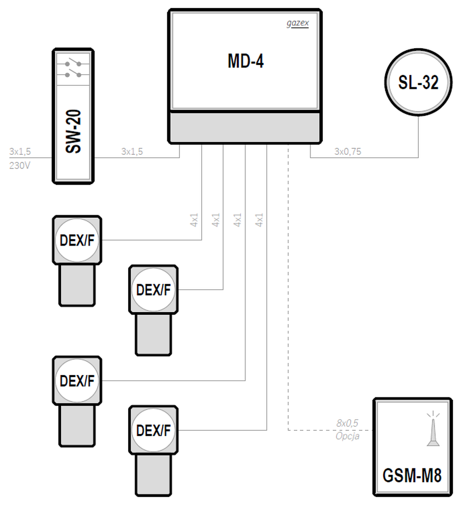
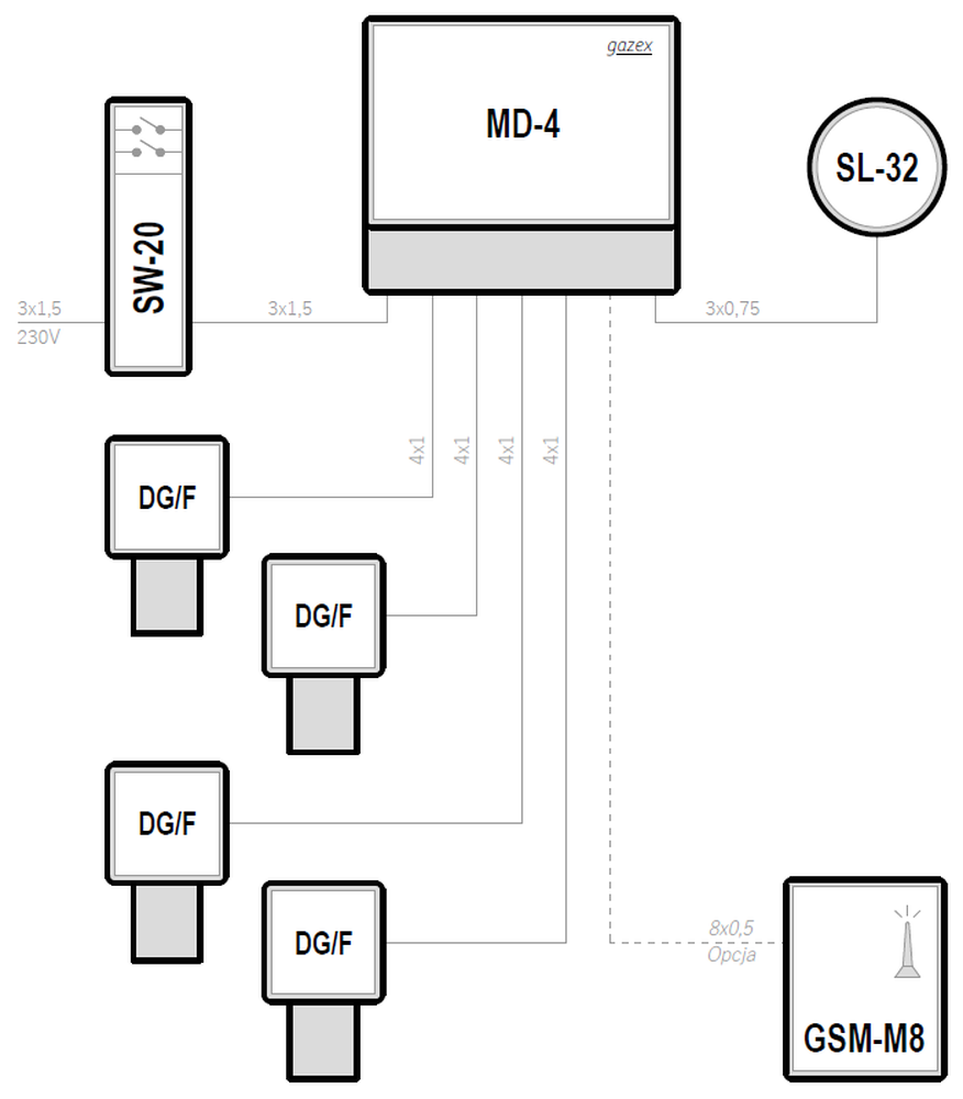
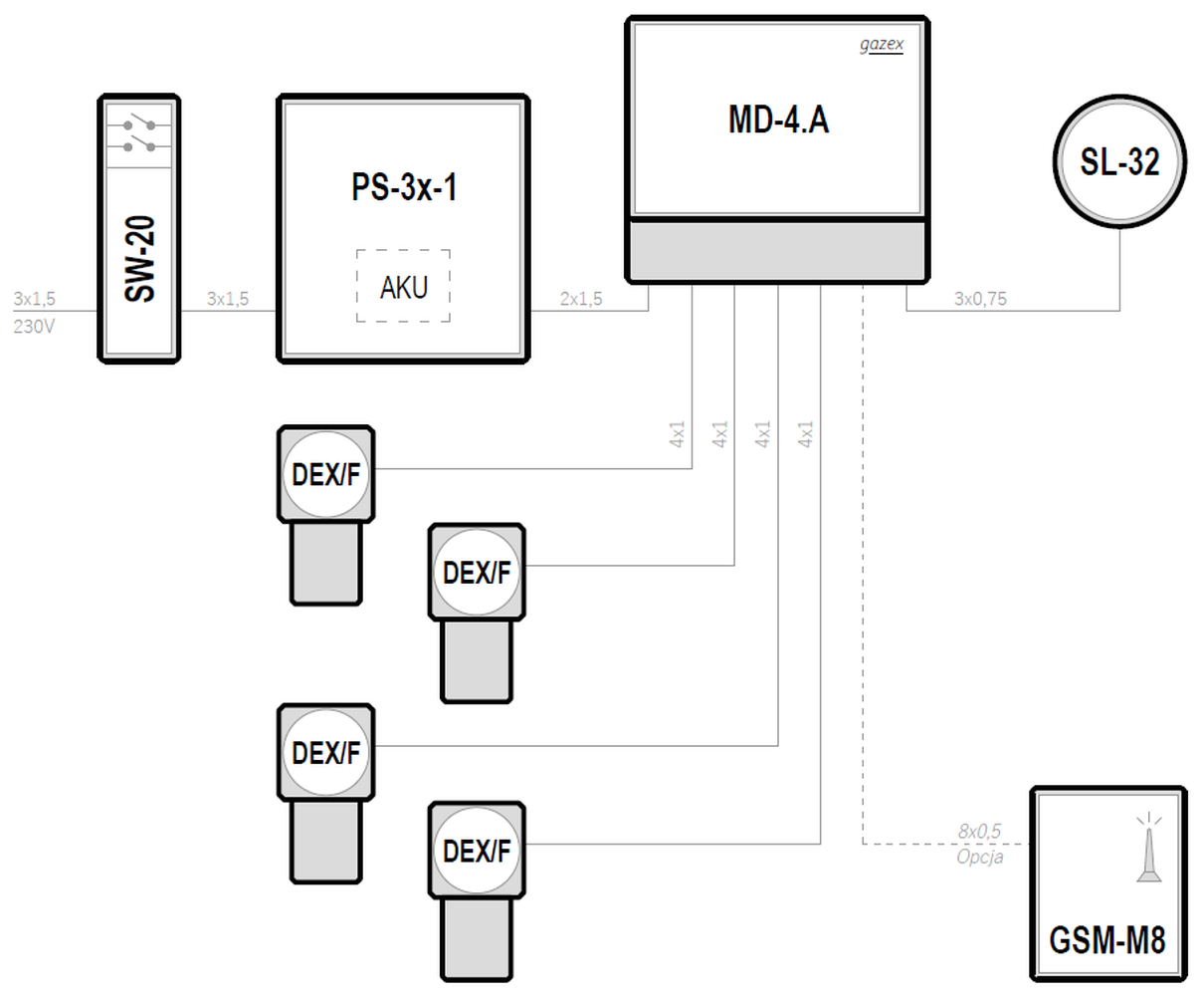
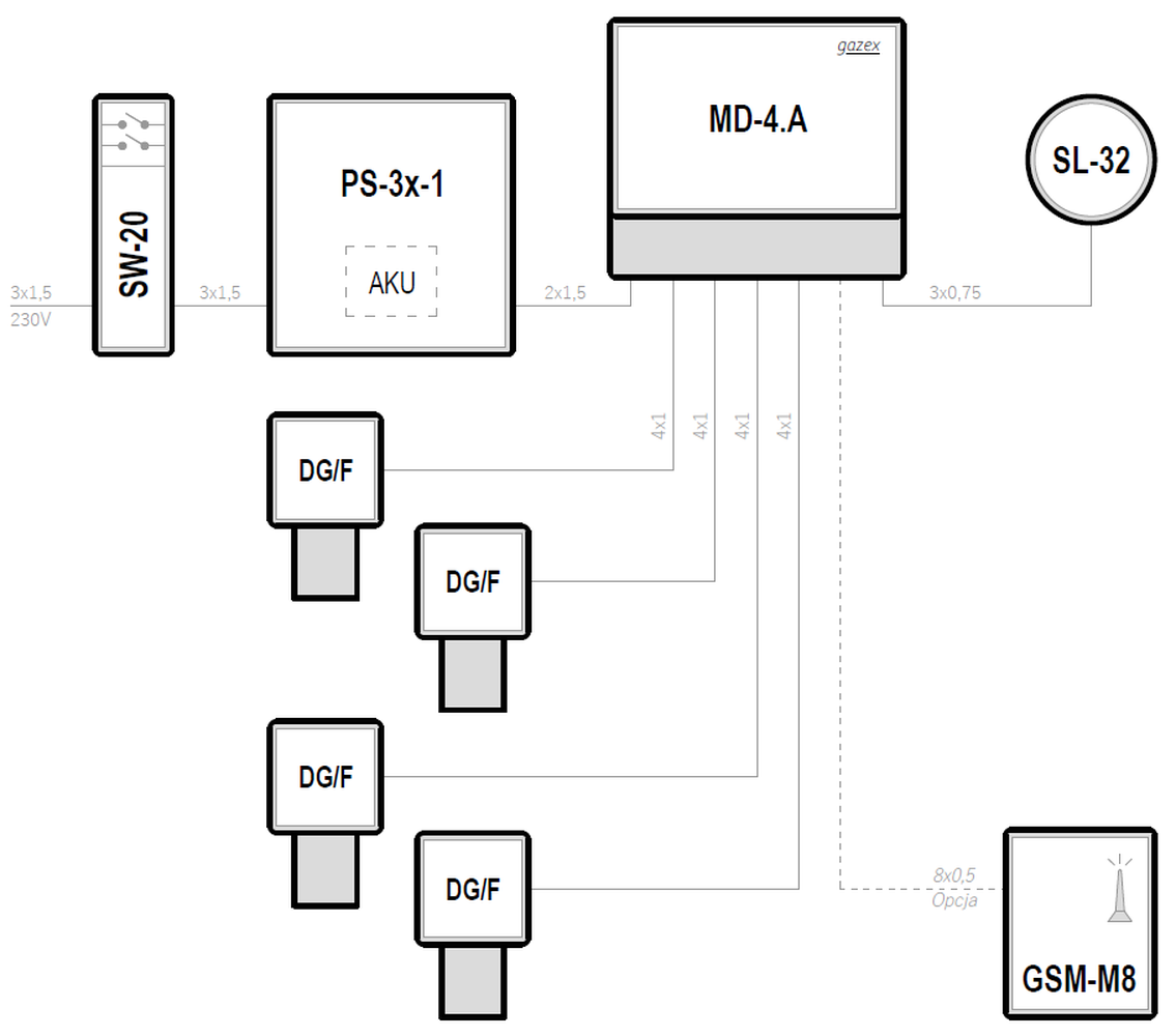
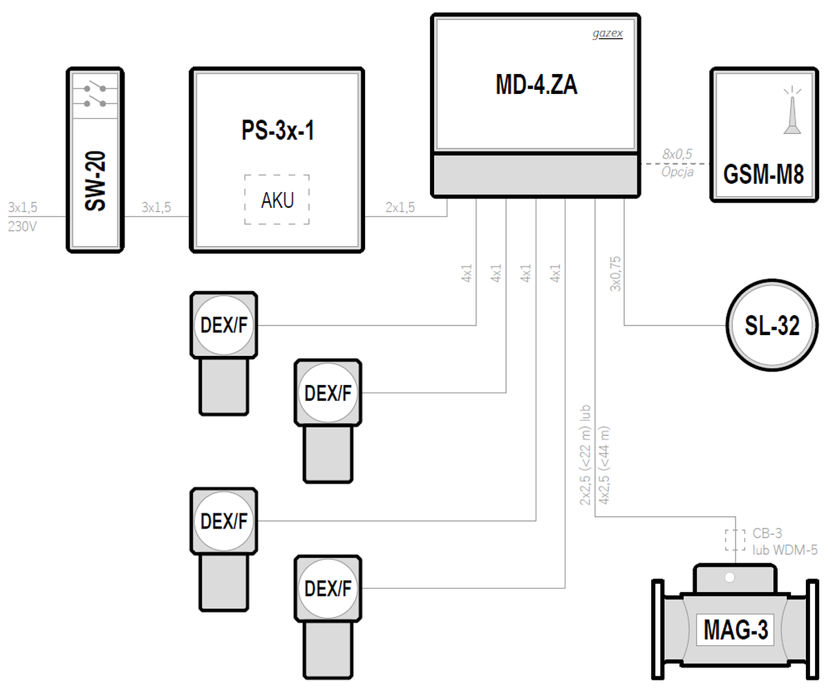
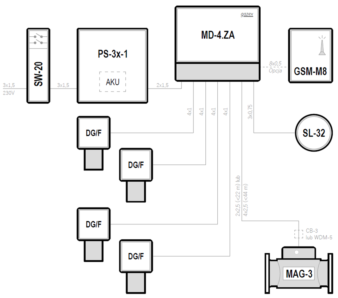
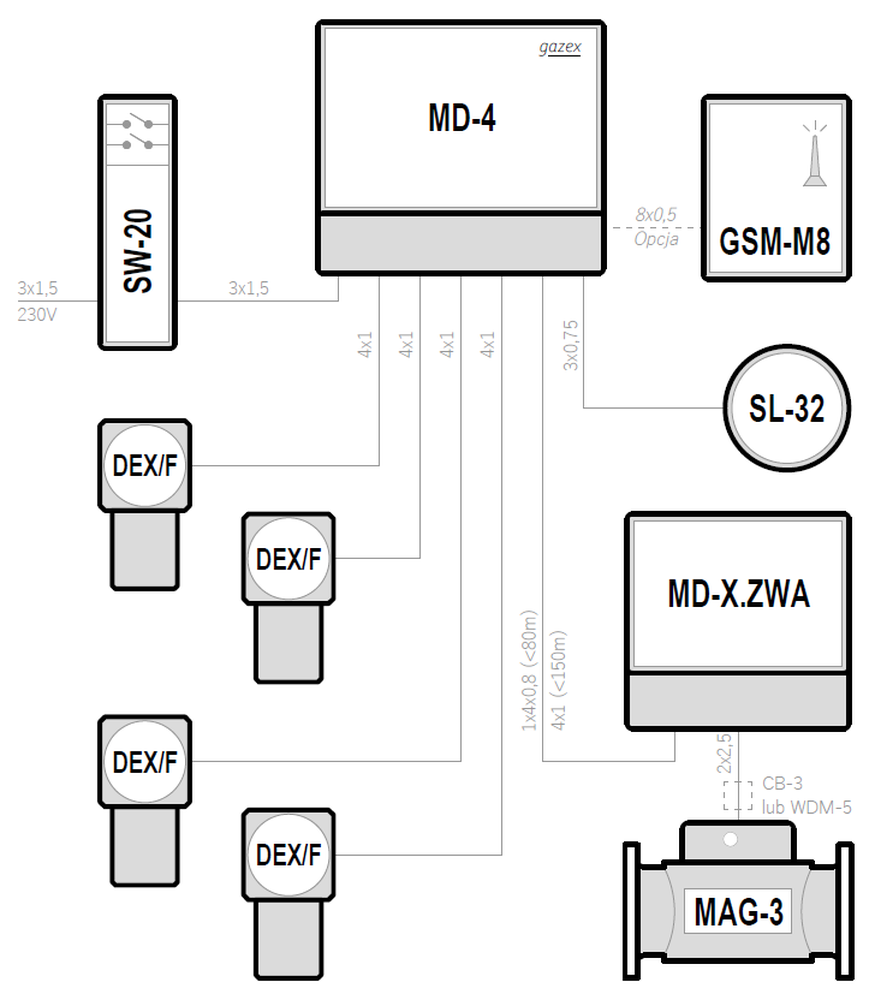
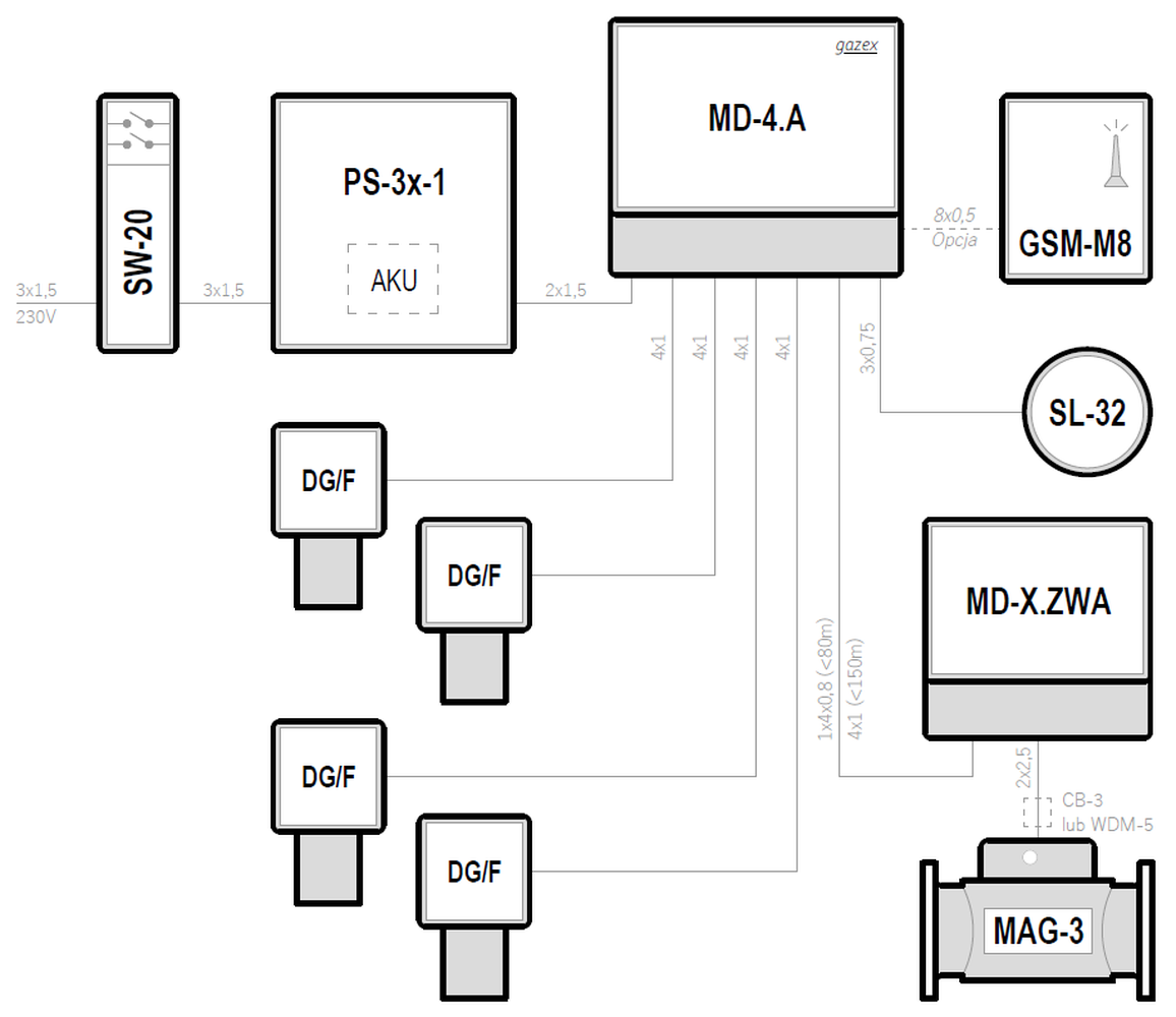
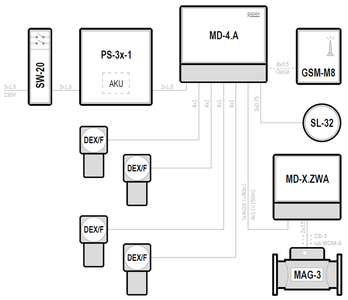
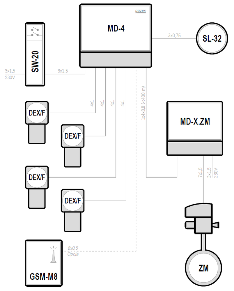
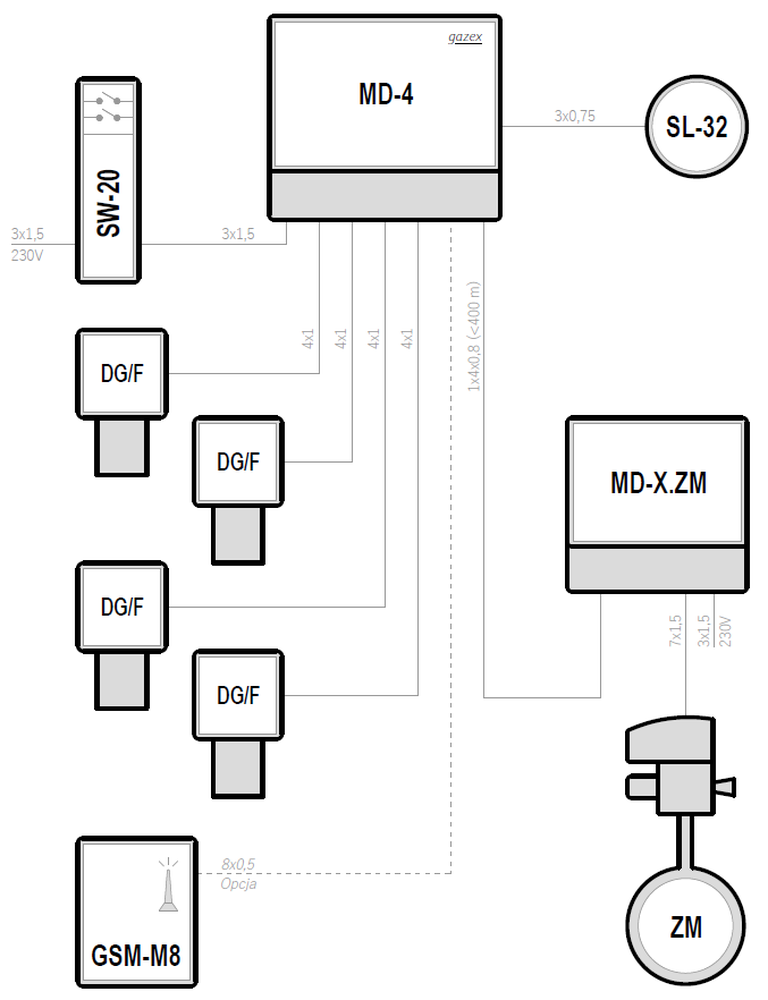
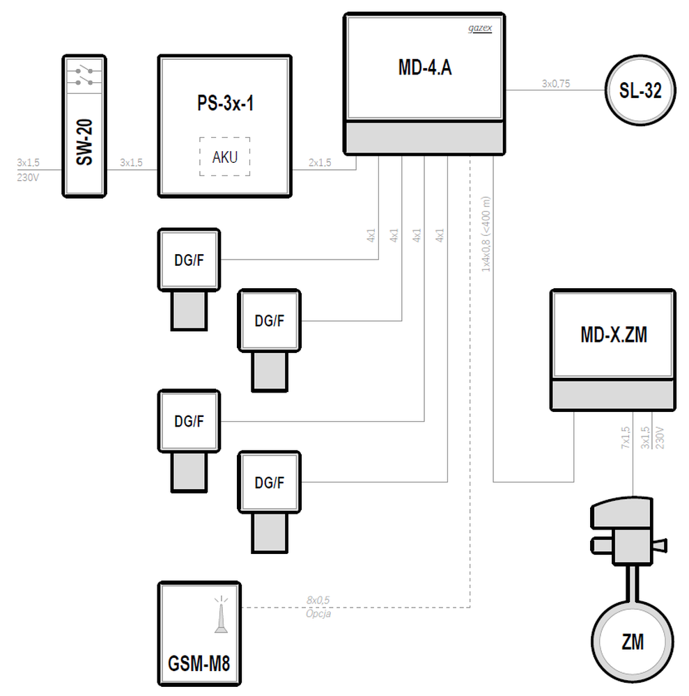
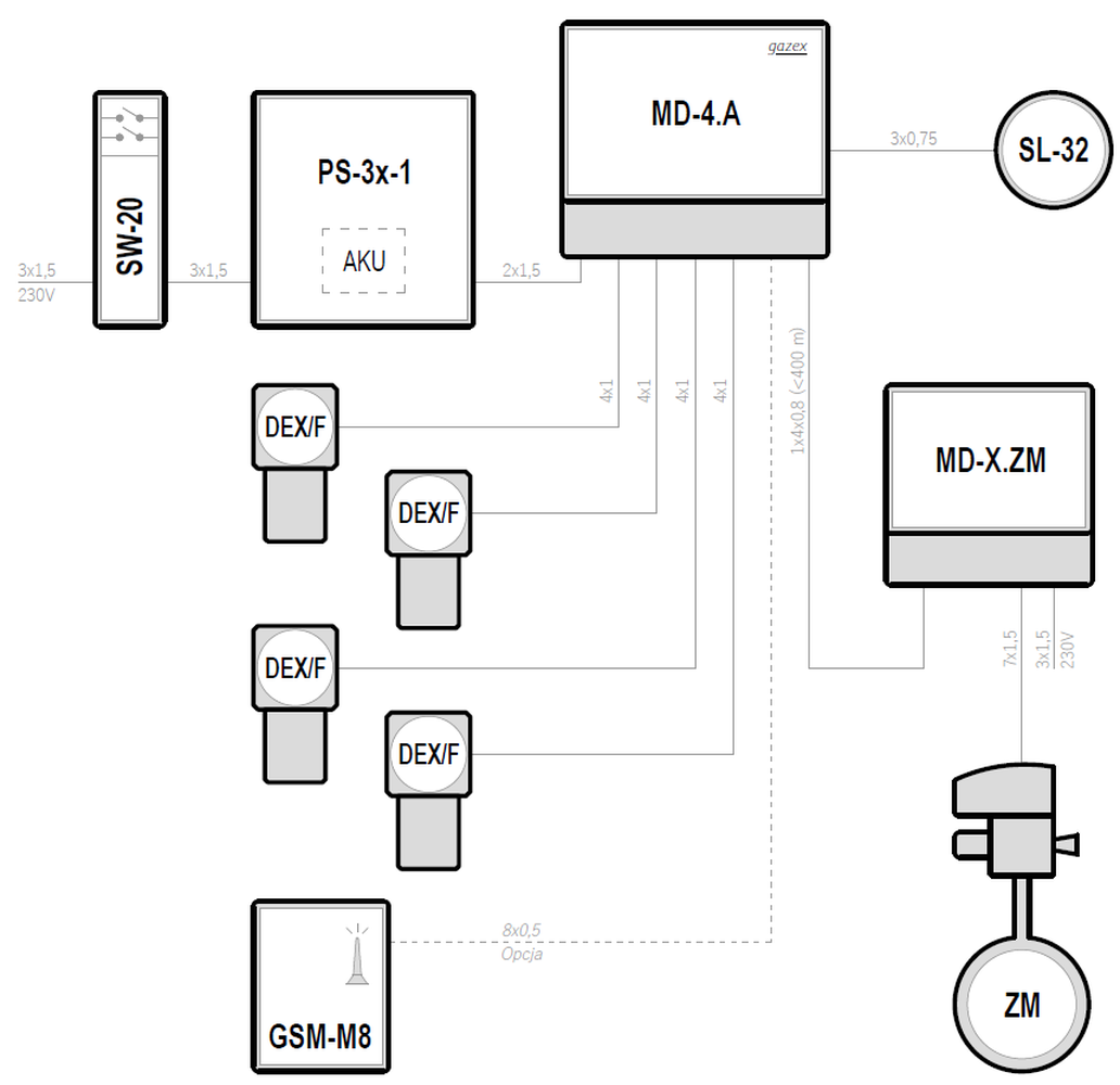
Systemy w oparciu o moduły sterujące typu MD-4
| Supply voltage | Control unit | Maximum number of gas detectors | Types of gas detectors | Emergency power backup | |
|---|---|---|---|---|---|
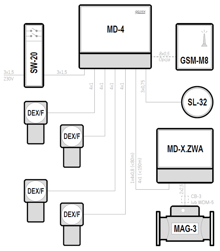
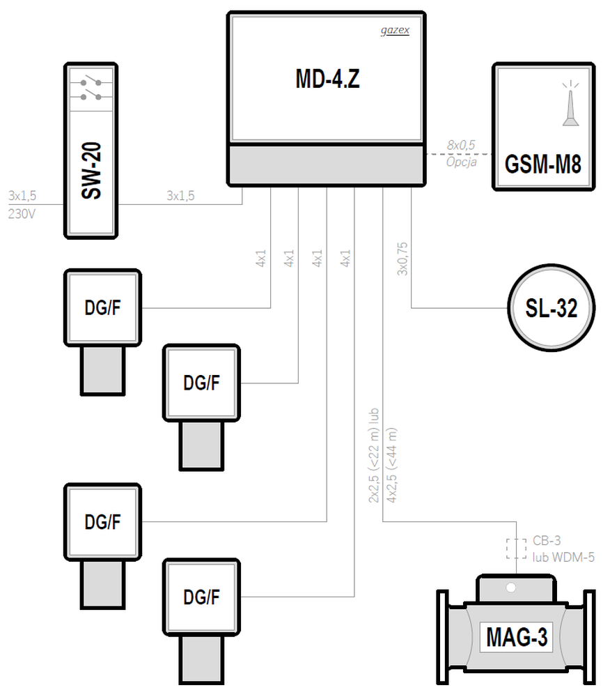
| 230VAC | MD-4 | 4 | DEX/F | — | Preview PDF DWG |
| 230VAC | MD-4 | 4 | DG/F | — | Preview PDF DWG |
| 12VDC | MD-4.A | 4 | DEX/F | ✓ | Preview PDF DWG |
| 12VDC | MD-4.A | 4 | DG/F | ✓ | Preview PDF DWG |
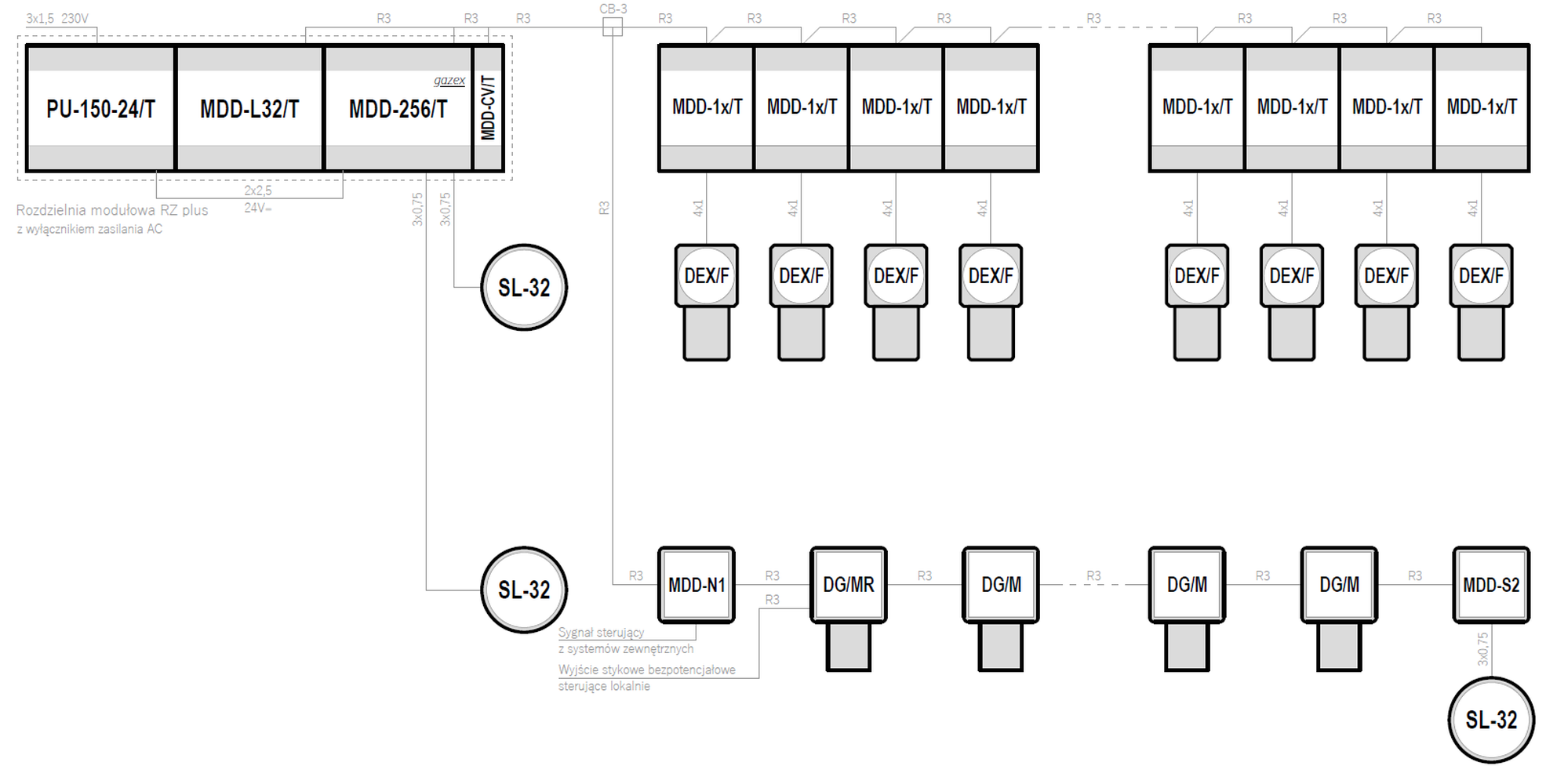
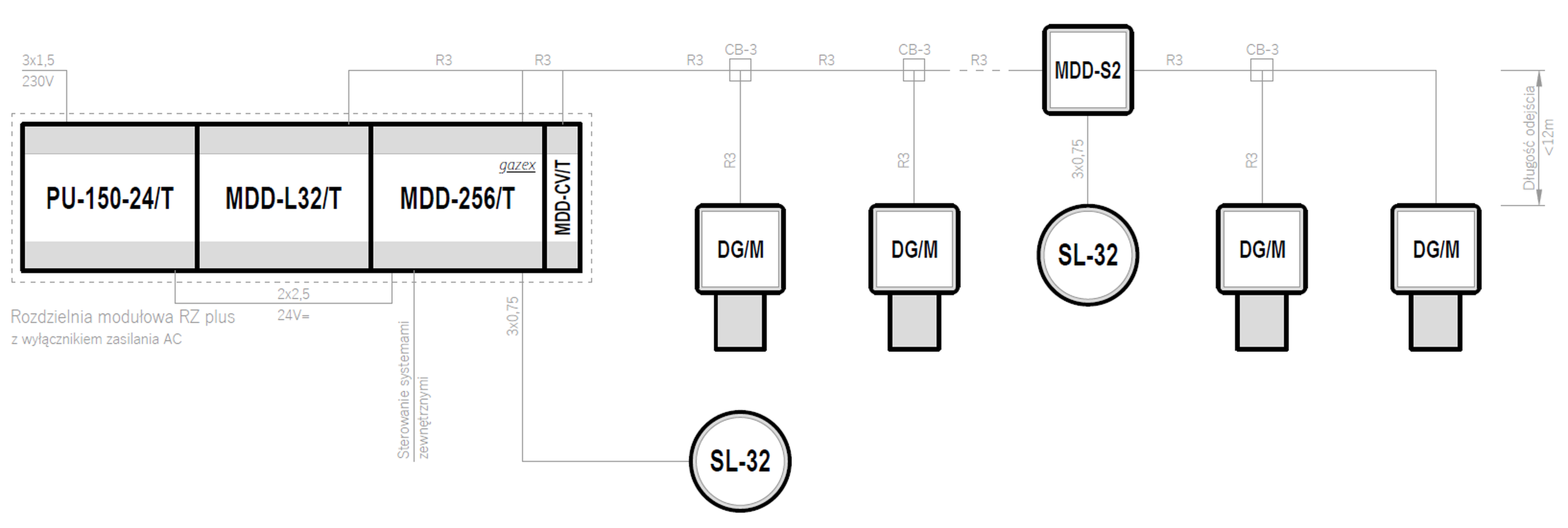
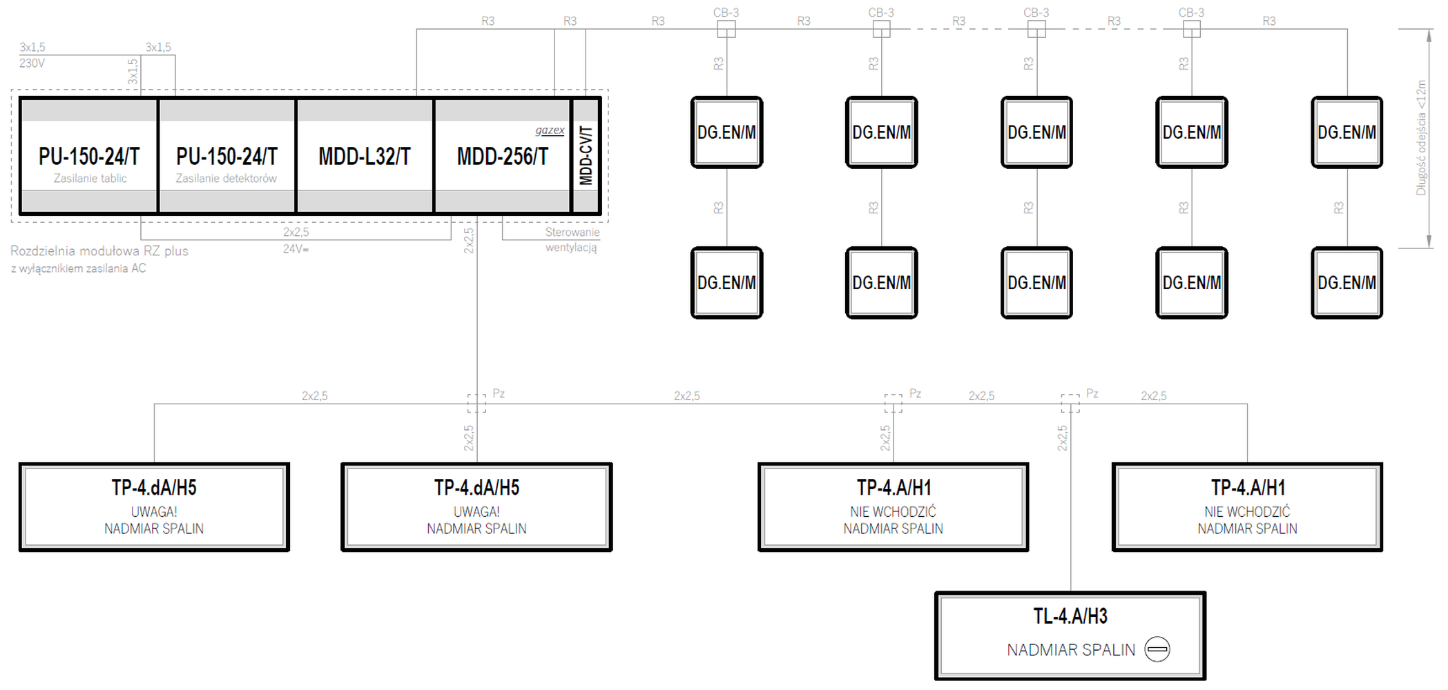
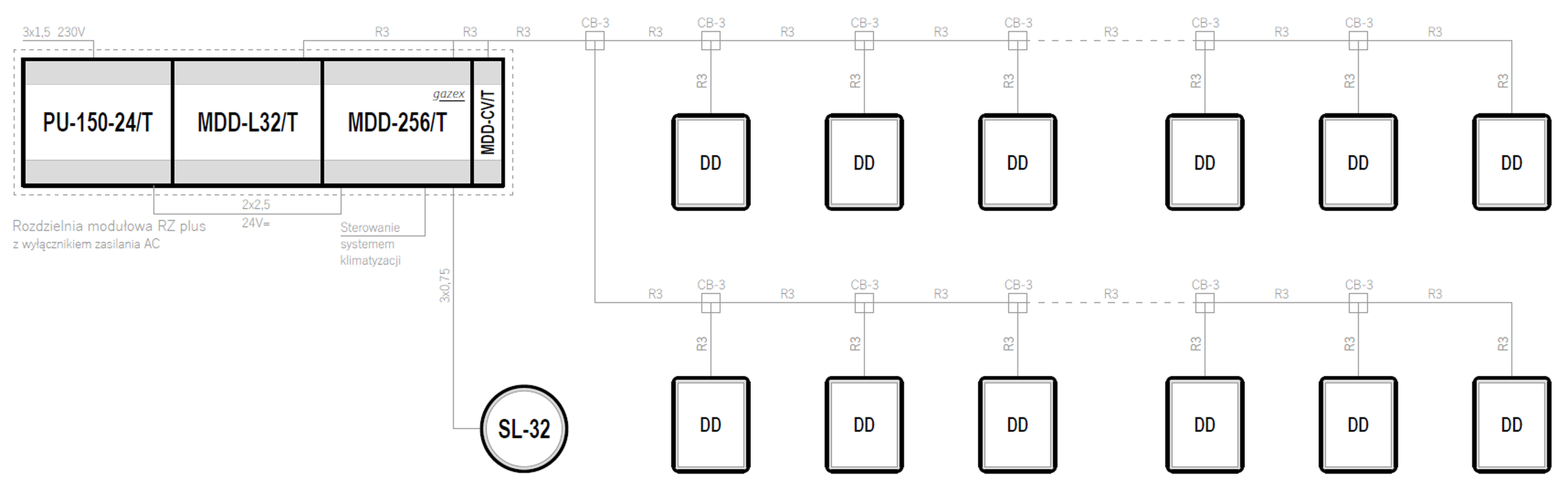
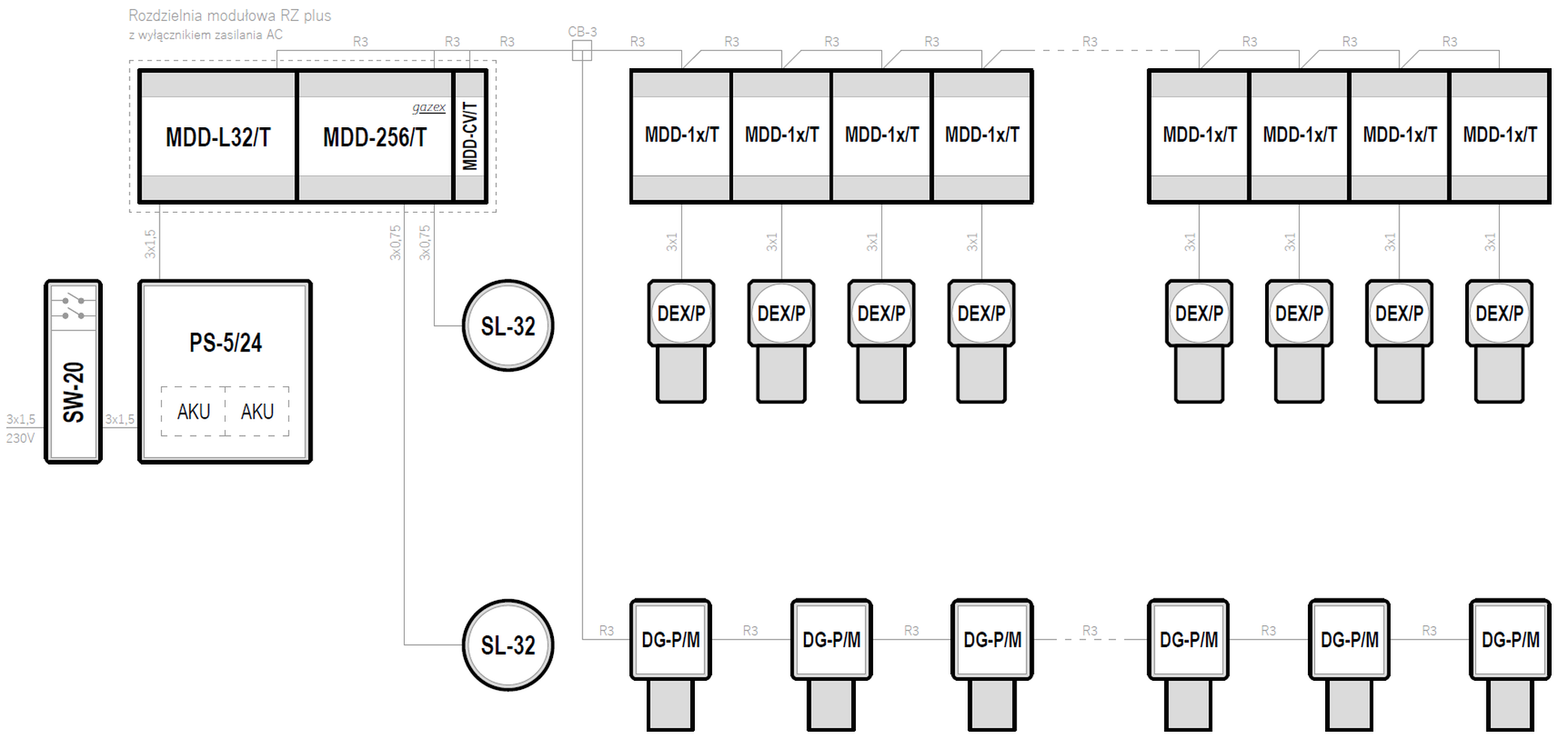
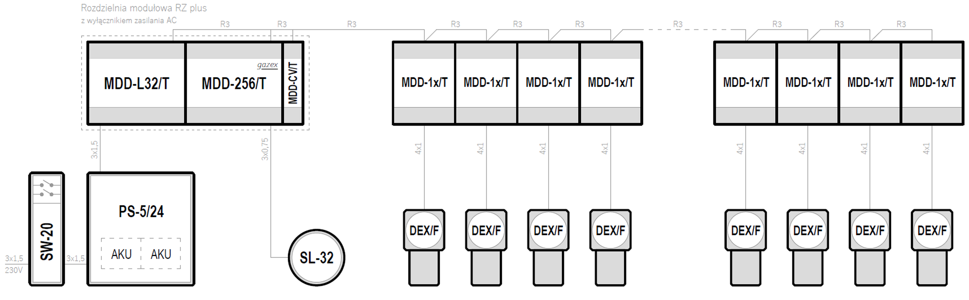
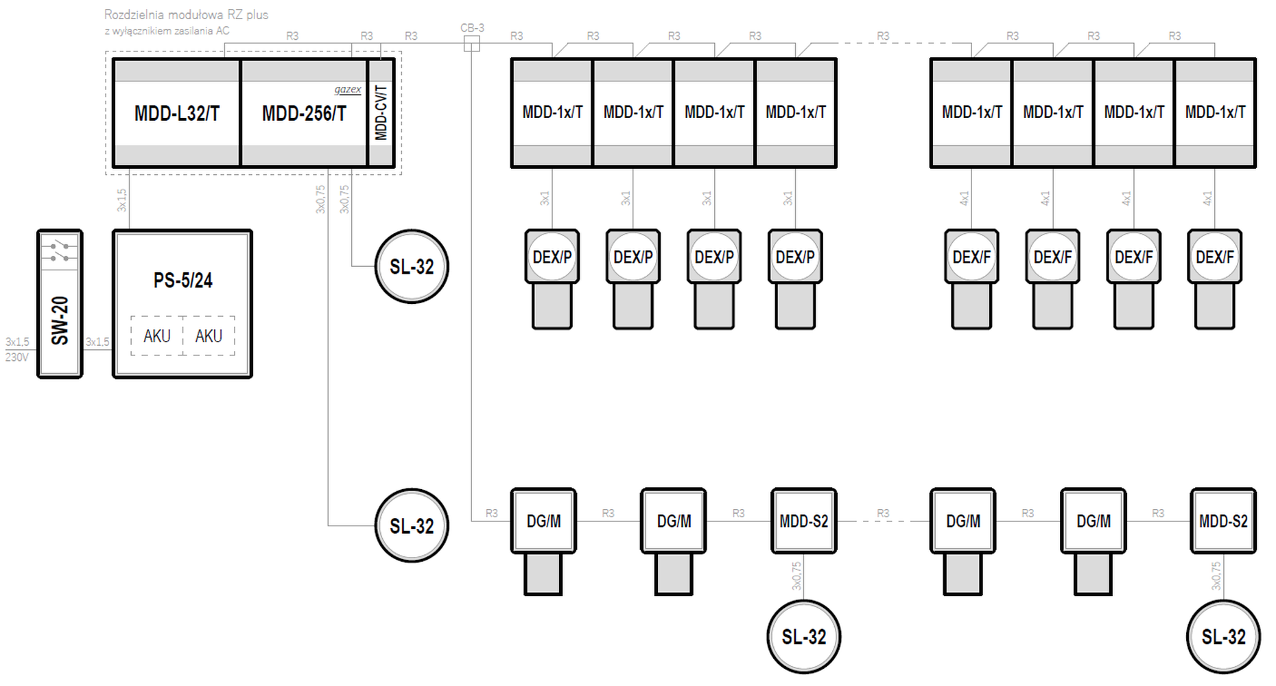
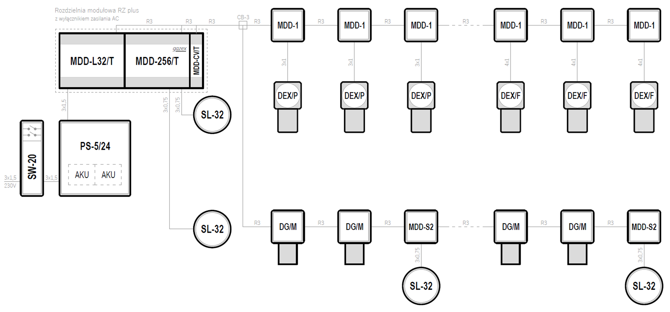
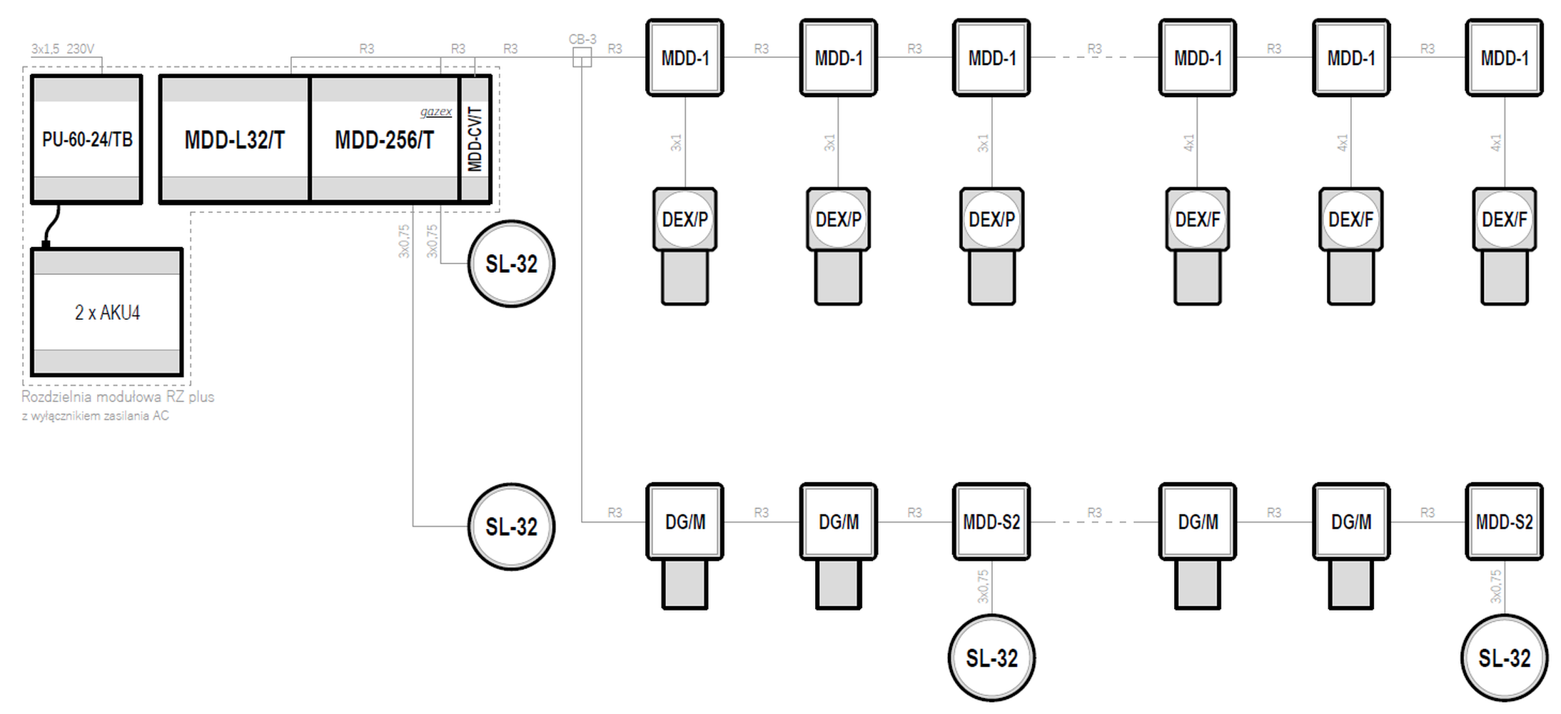
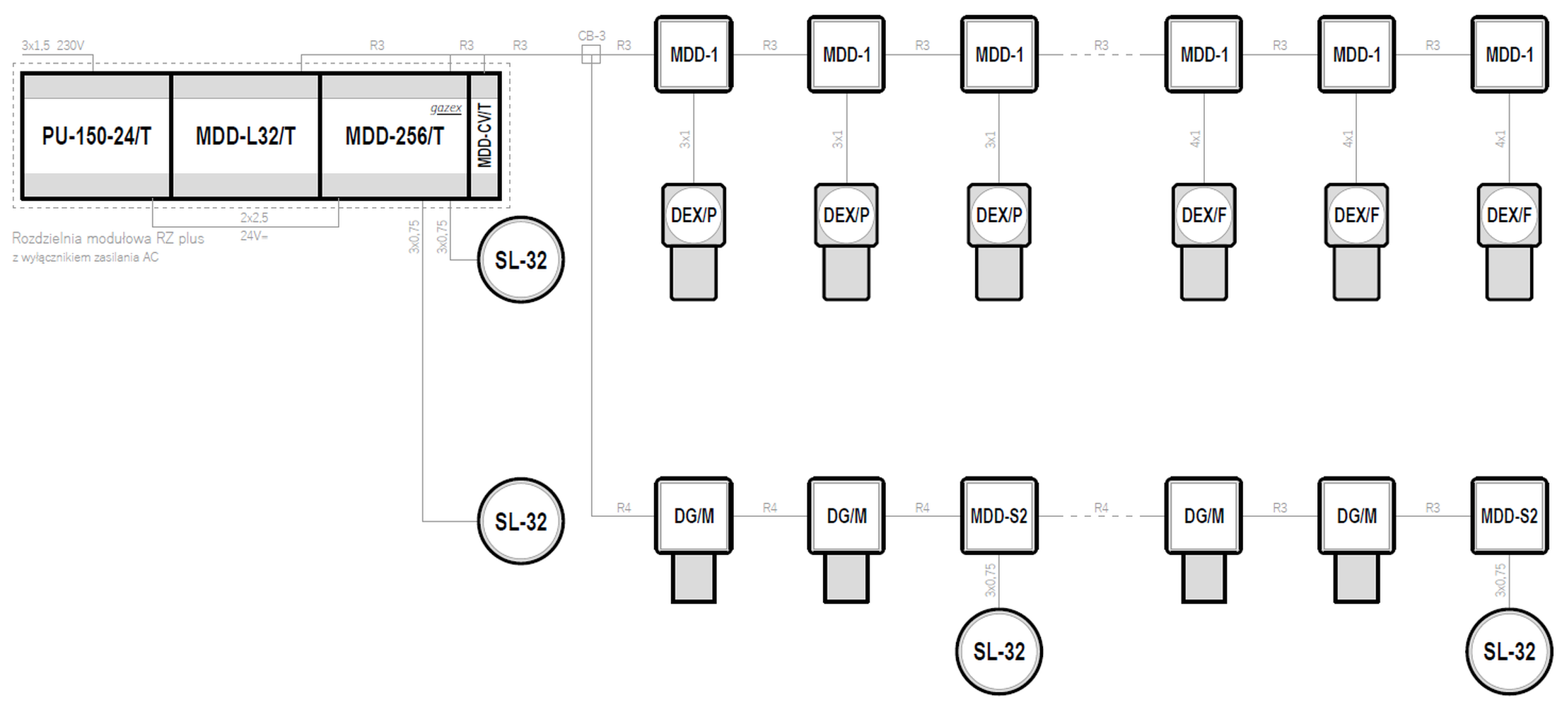
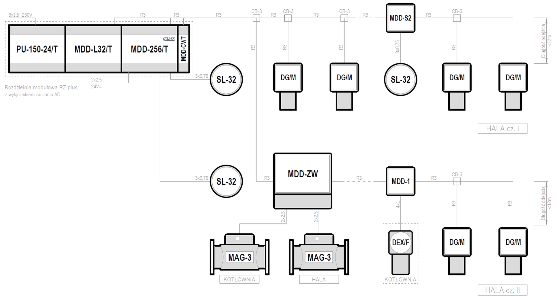
Systemy w oparciu o moduł sterujący MDD-256/T - podłączenie detektorów serii DEX za pośrednictwem modułów MDD-1x/T
| Supply voltage | Control unit | Maximum number of gas detectors | Types of gas detectors | Emergency power backup | |
|---|---|---|---|---|---|
| 24VDC | MDD-256/T | 224 |
DEX/F DG/M DEX/P |
✓ | Preview PDF DWG |
| 24VDC | MDD-256/T | 224 |
DEX/F DG/M DEX/P |
✓ | Preview PDF DWG |
| 24VDC | MDD-256/T | 224 |
DEX/F DG/M DEX/P |
— | Preview PDF DWG |
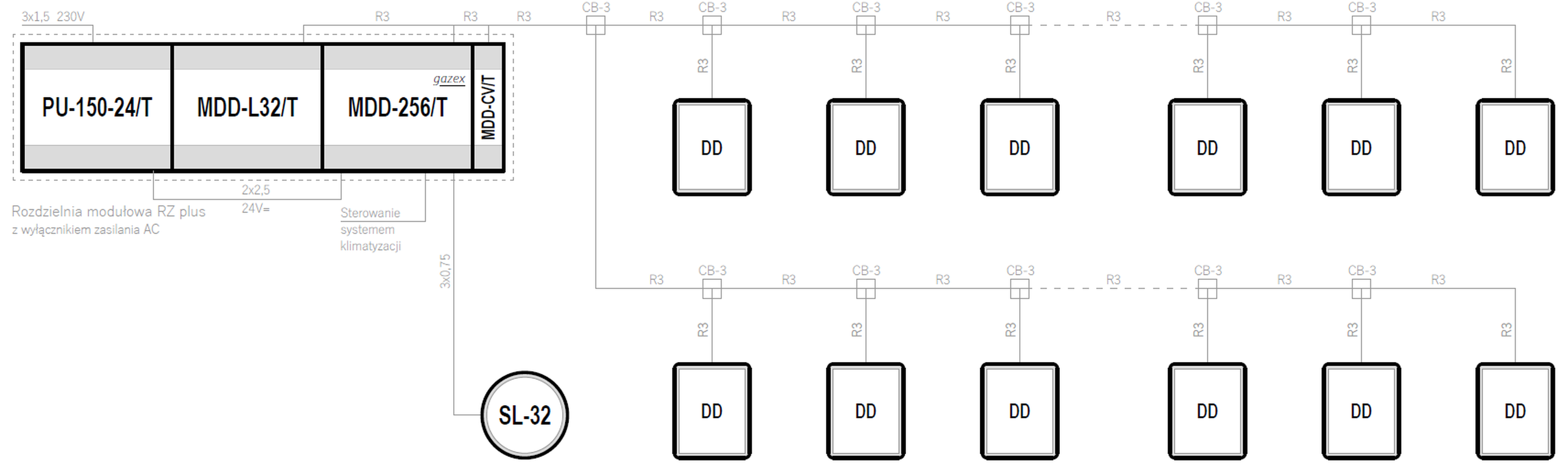
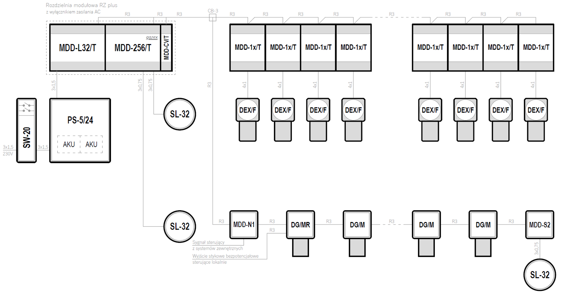
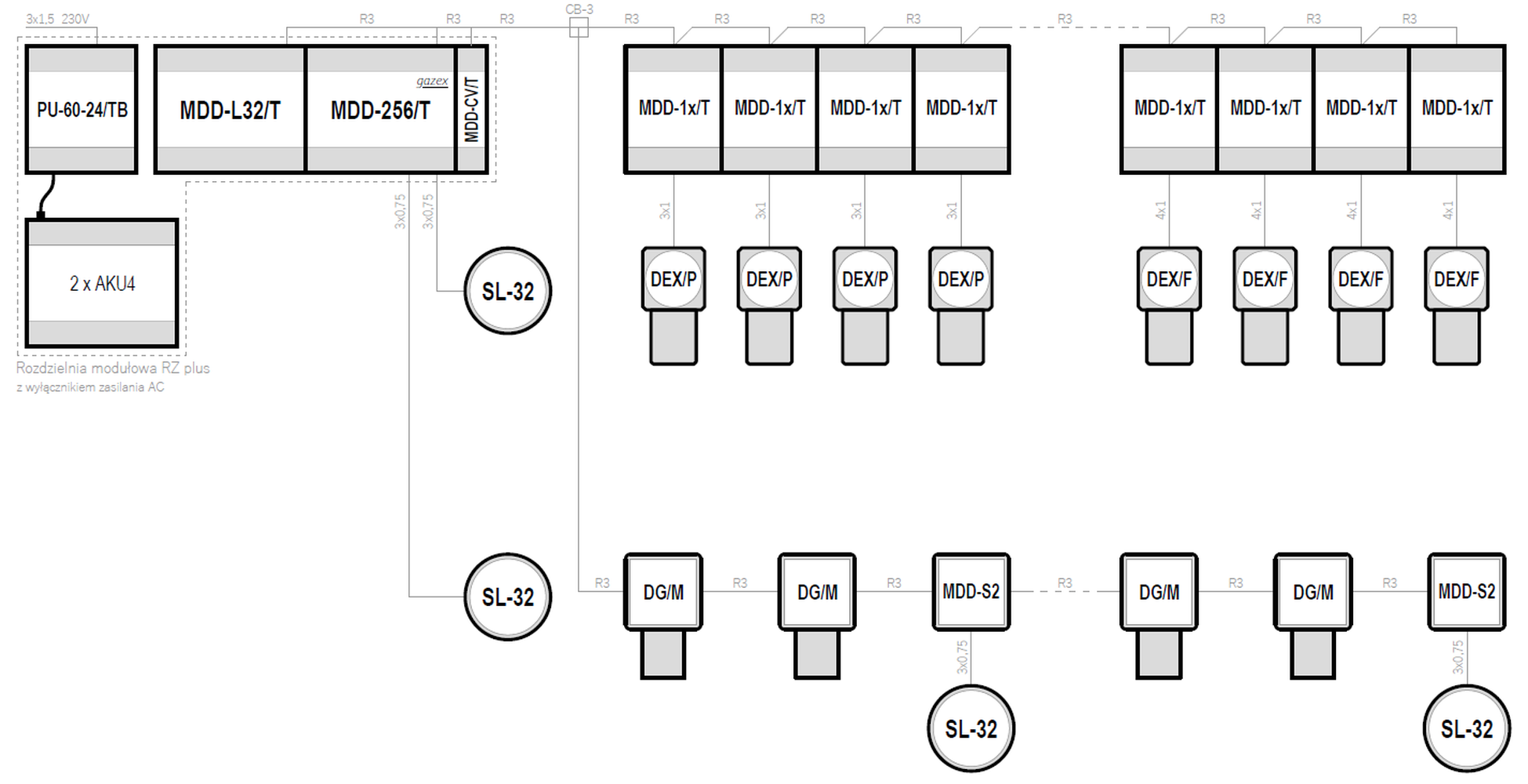
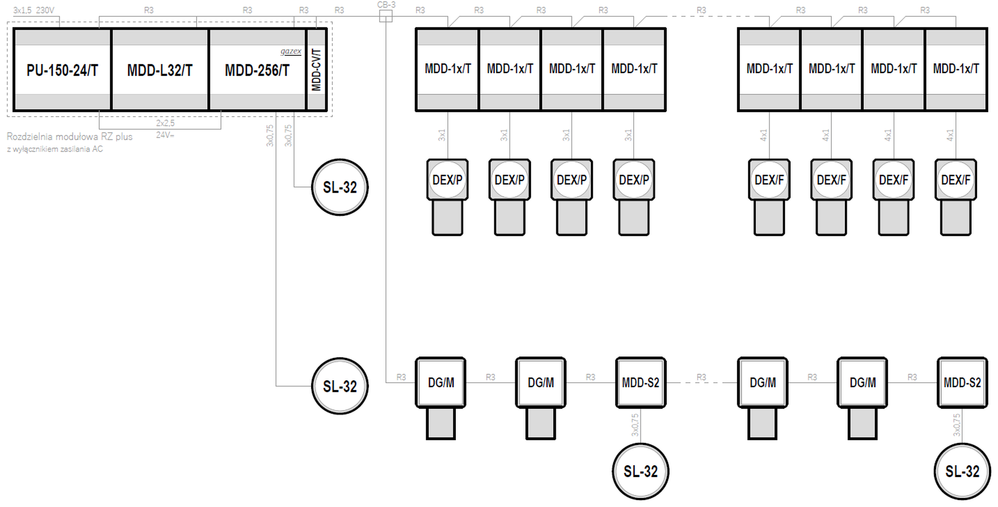
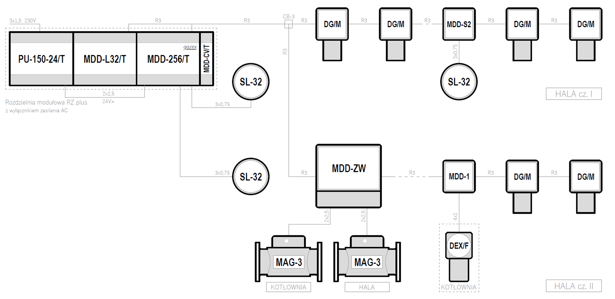
Systemy w oparciu o moduł sterujący MDD-256/T - podłączenie detektorów serii DEX za pośrednictwem modułów MDD-1
| Supply voltage | Control unit | Maximum number of gas detectors | Types of gas detectors | Emergency power backup | |
|---|---|---|---|---|---|
| 24VDC | MDD-256/T | 224 |
DEX/F DG/M DEX/P |
✓ | Preview PDF DWG |
| 24VDC | MDD-256/T | 224 |
DEX/F DG/M DEX/P |
✓ | Preview PDF DWG |
| 24VDC | MDD-256/T | 224 |
DEX/F DG/M DEX/P |
— | Preview PDF DWG |
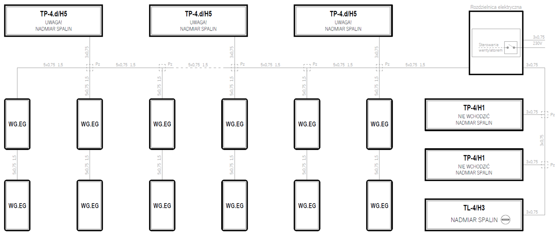
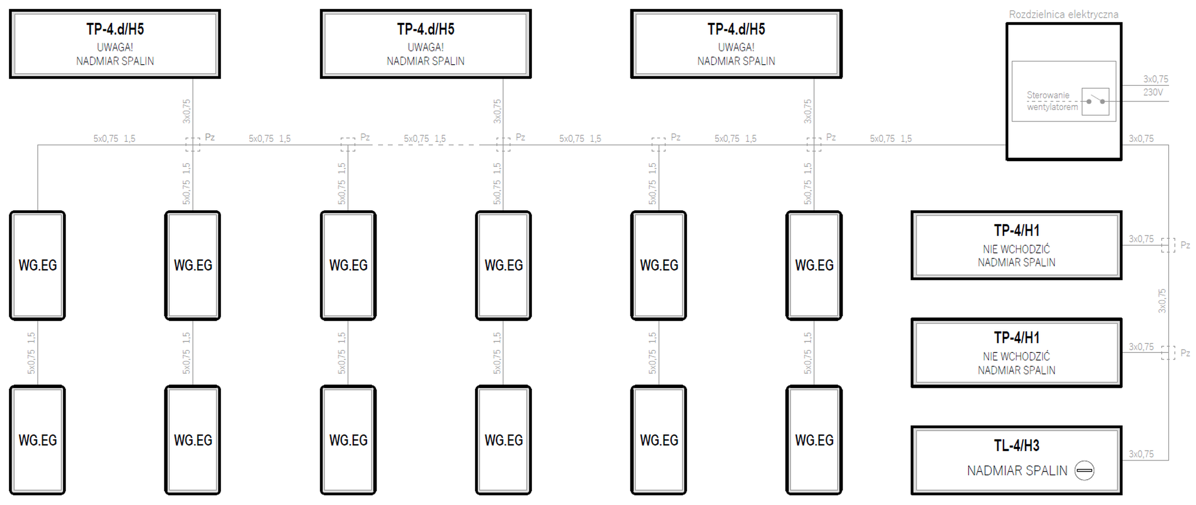
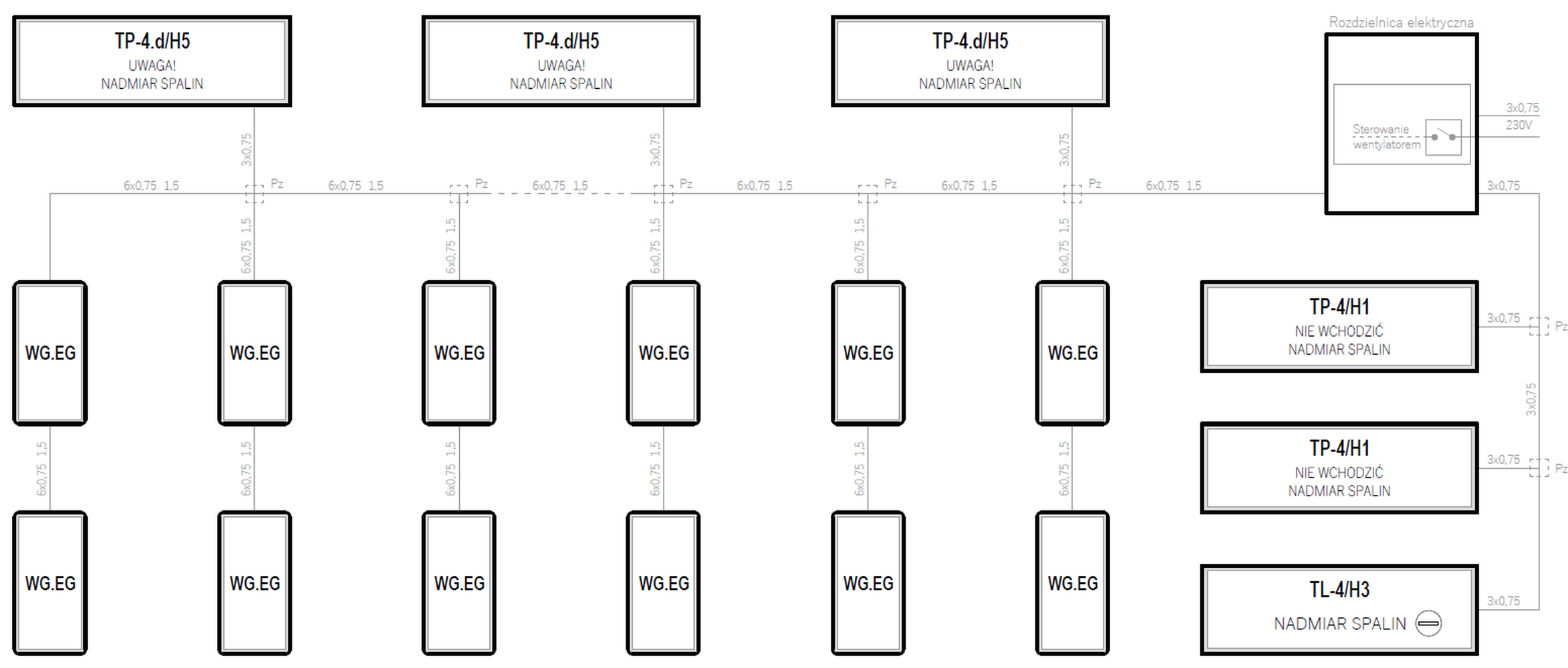
Systemy w oparciu o detektory typu WG.EG
| Supply voltage | Control unit | Maximum number of gas detectors | Types of gas detectors | Emergency power backup | |
|---|---|---|---|---|---|
| 230VAC | — | ∞ | WG.EG | — | Preview PDF DWG |
| 230VAC | — | ∞ | WG.EG | — | Preview PDF DWG |
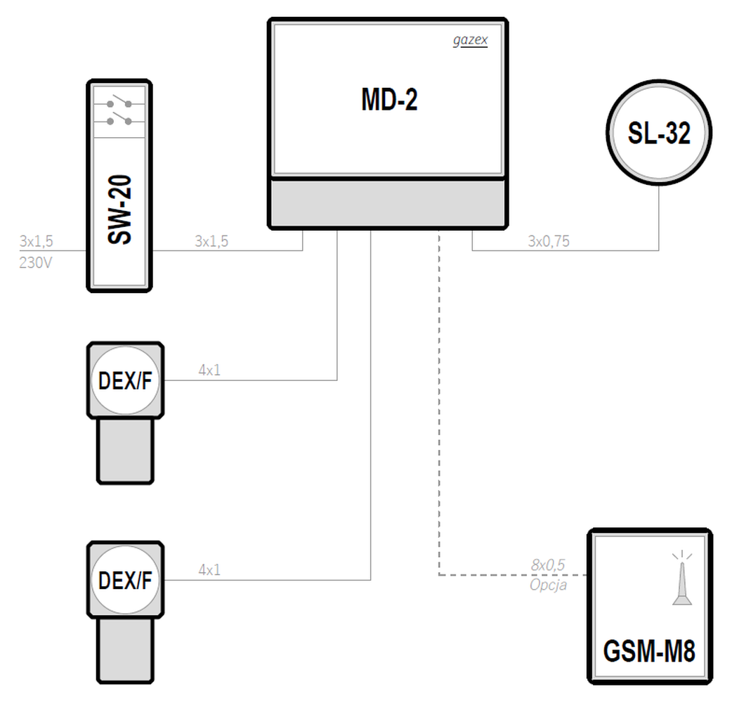
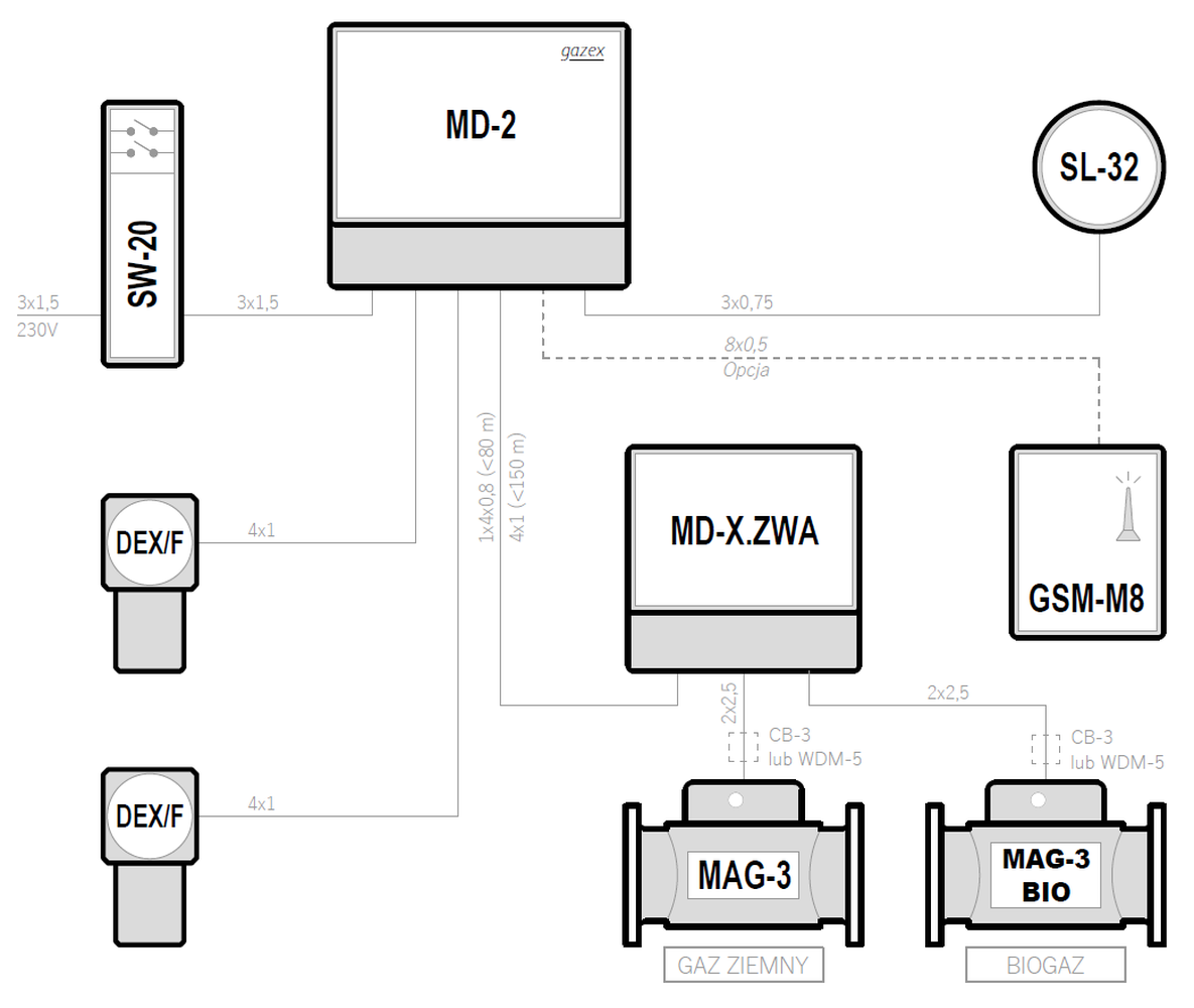
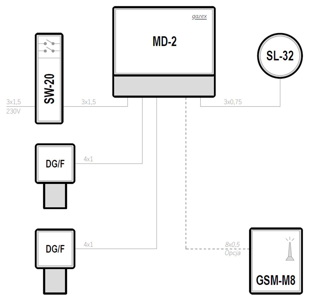
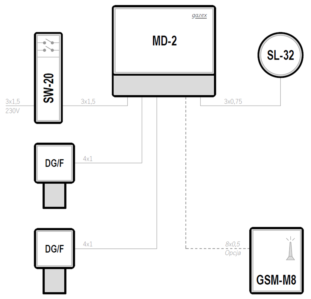
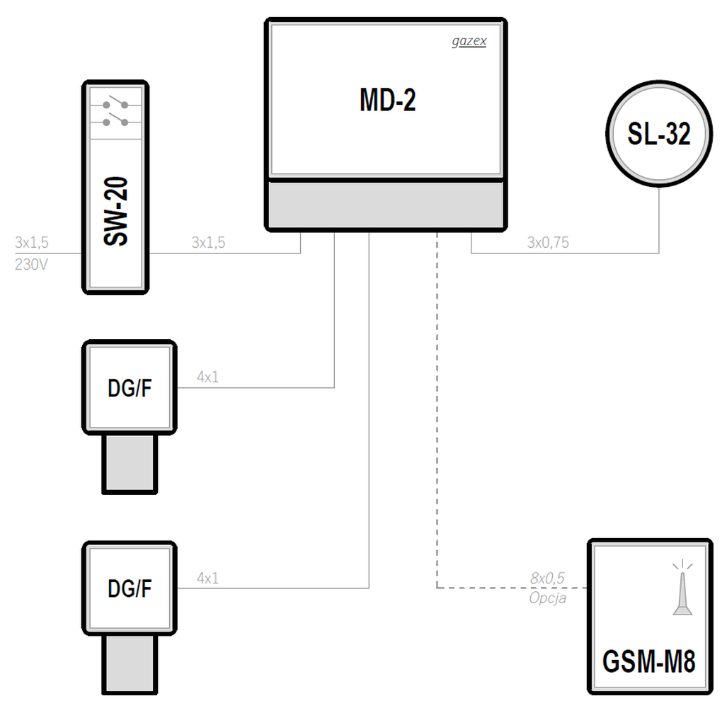
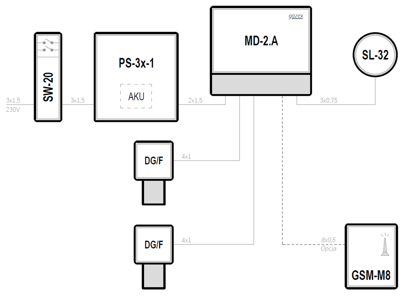
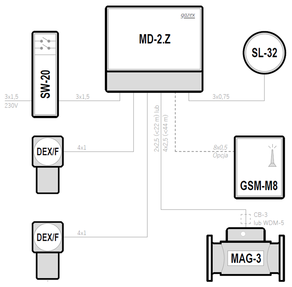
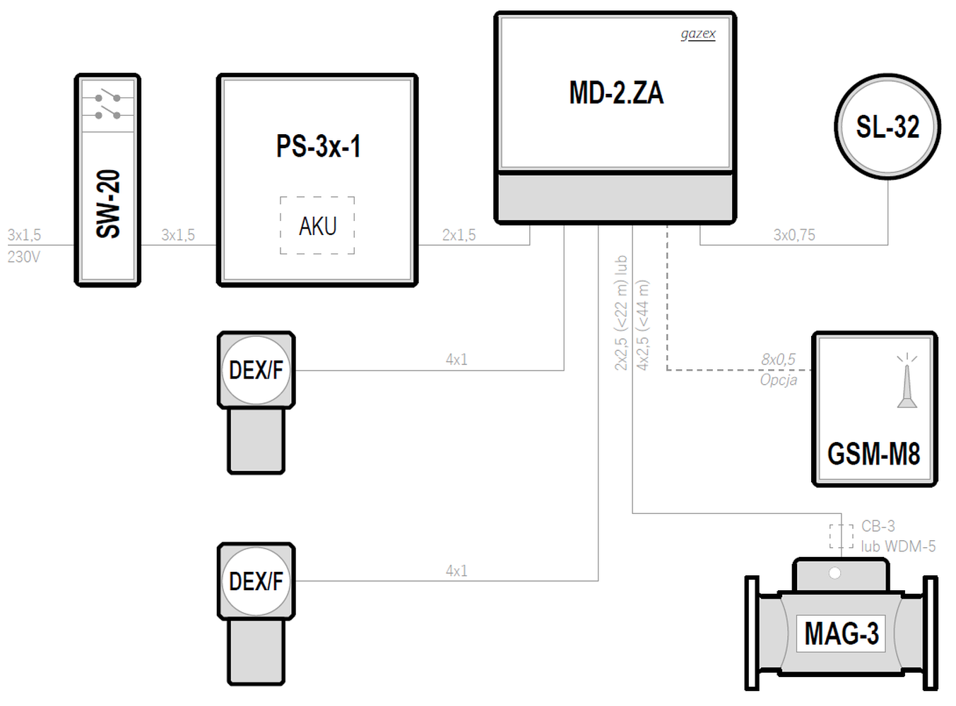
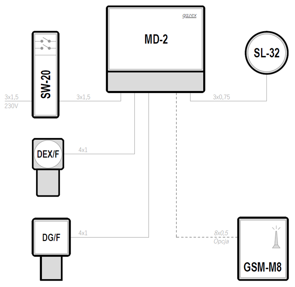
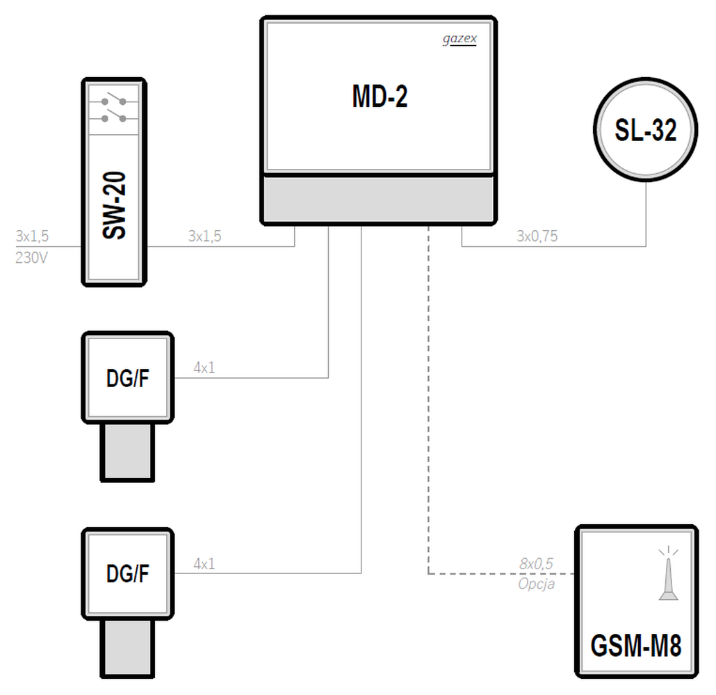
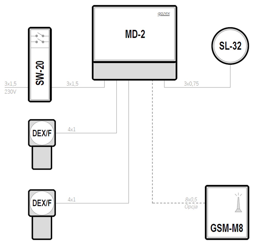
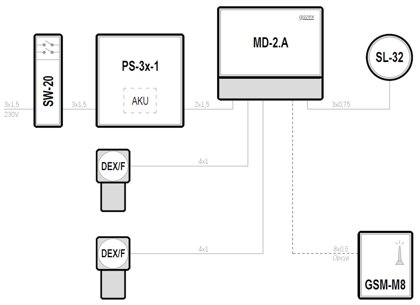
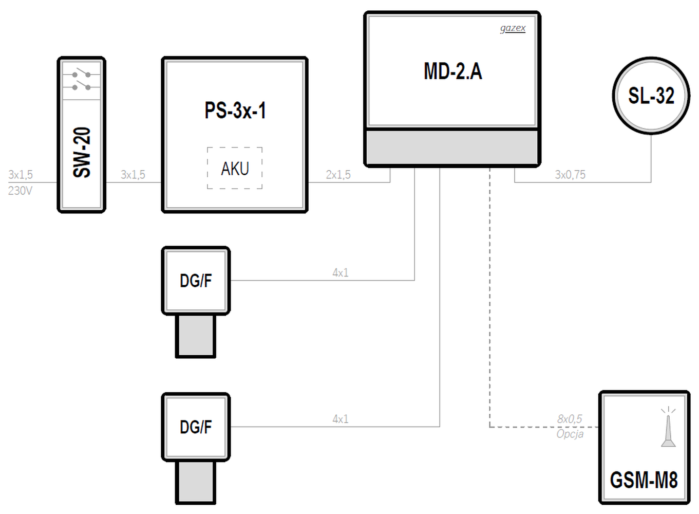
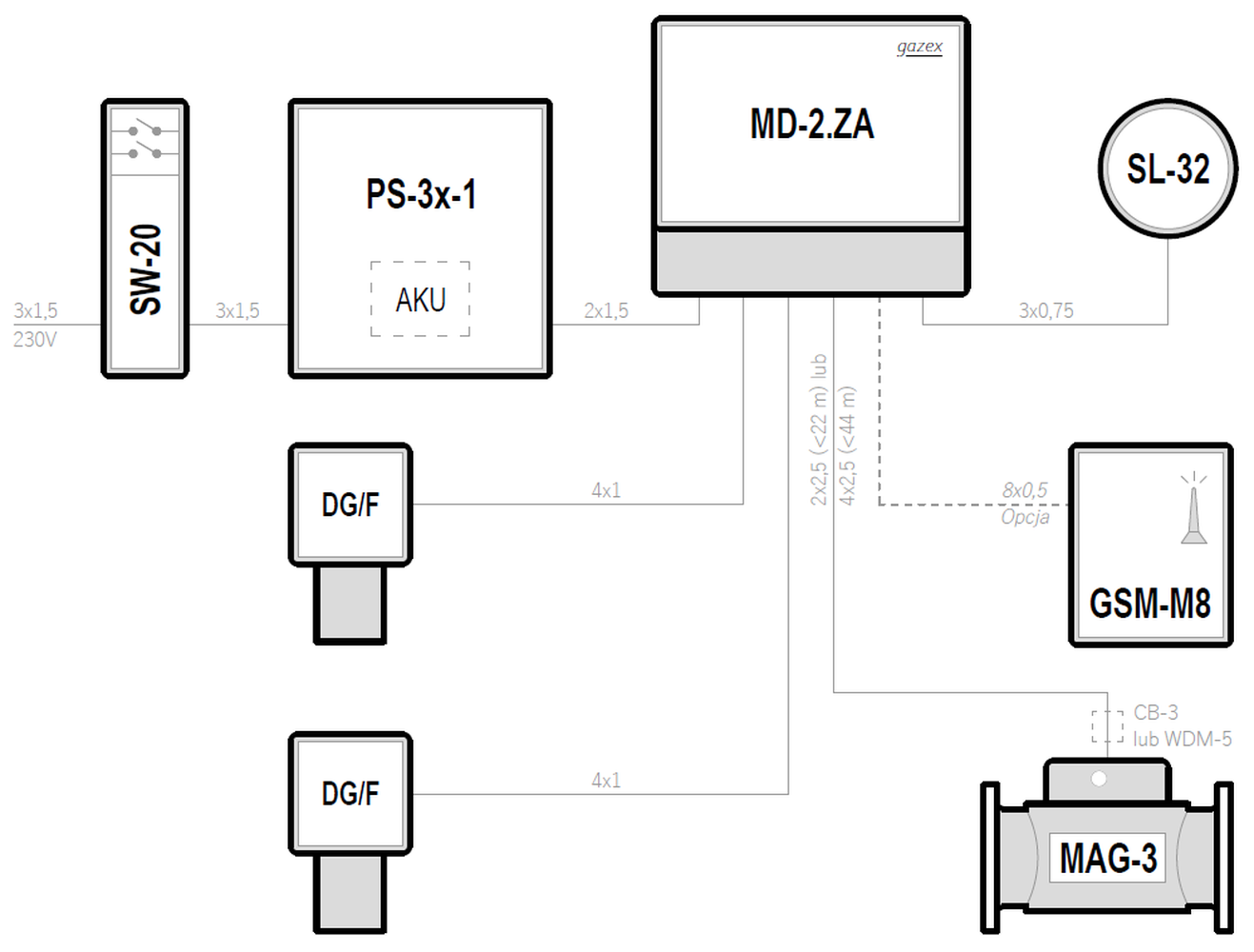
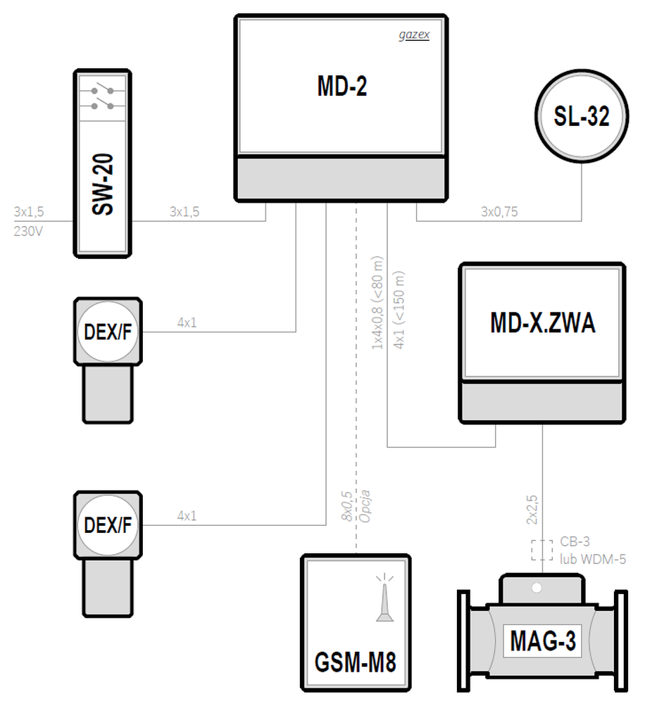
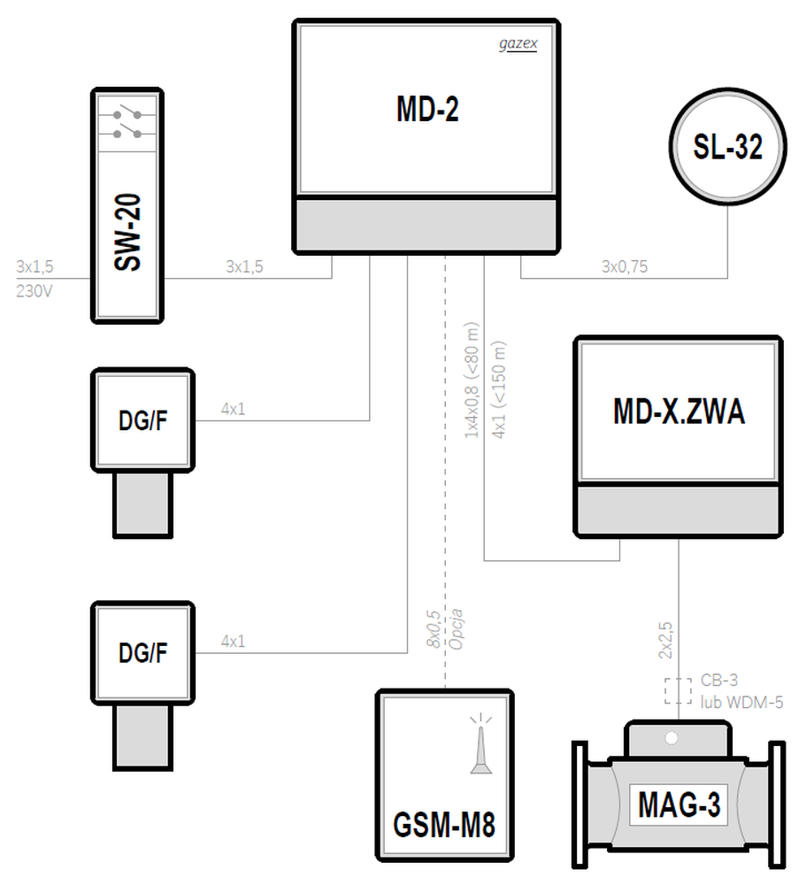
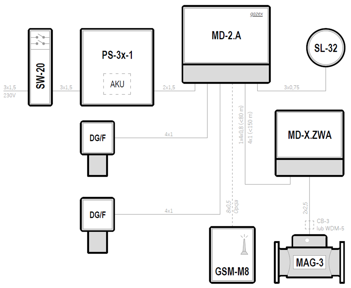
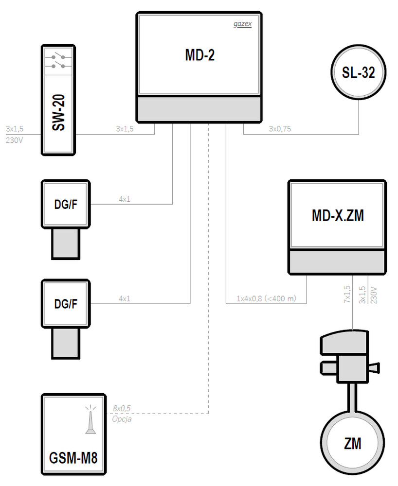
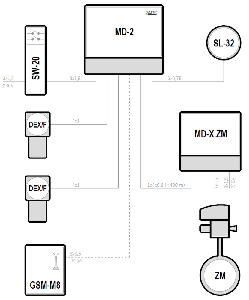
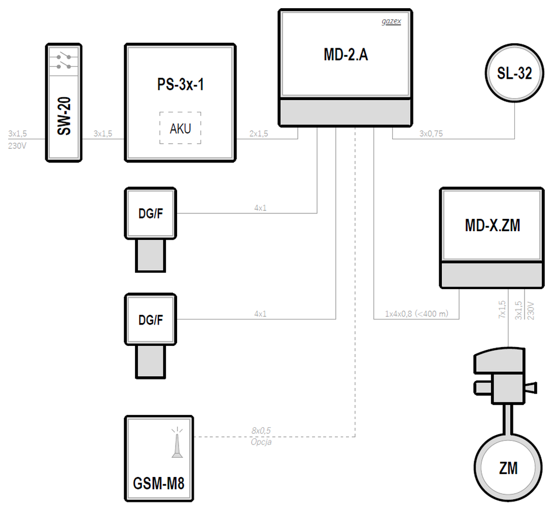
Systemy w oparciu o moduły sterujące typu MD-2
| Supply voltage | Control unit | Maximum number of gas detectors | Types of gas detectors | Emergency power backup | |
|---|---|---|---|---|---|
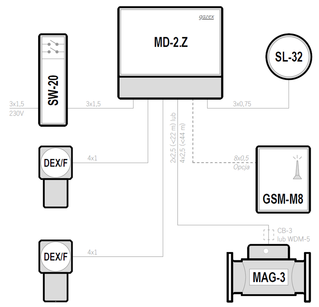
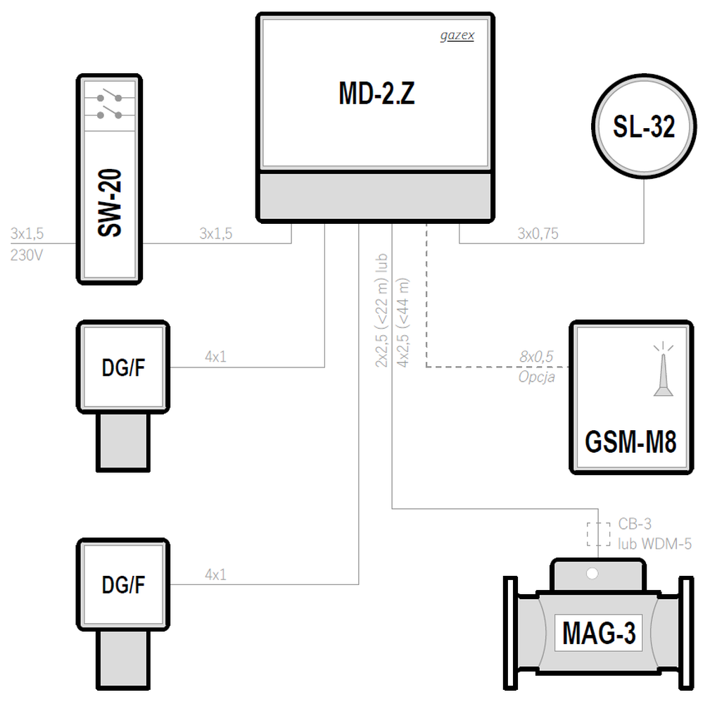
| 230VAC | MD-2 | 2 | DEX/F | — | Preview PDF DWG |
| 230VAC | MD-2 | 2 | DG/F | — | Preview PDF DWG |
| 12VDC | MD-2.A | 2 | DEX/F | ✓ | Preview PDF DWG |
| 12VDC | MD-2.A | 2 | DG/F | ✓ | Preview PDF DWG |
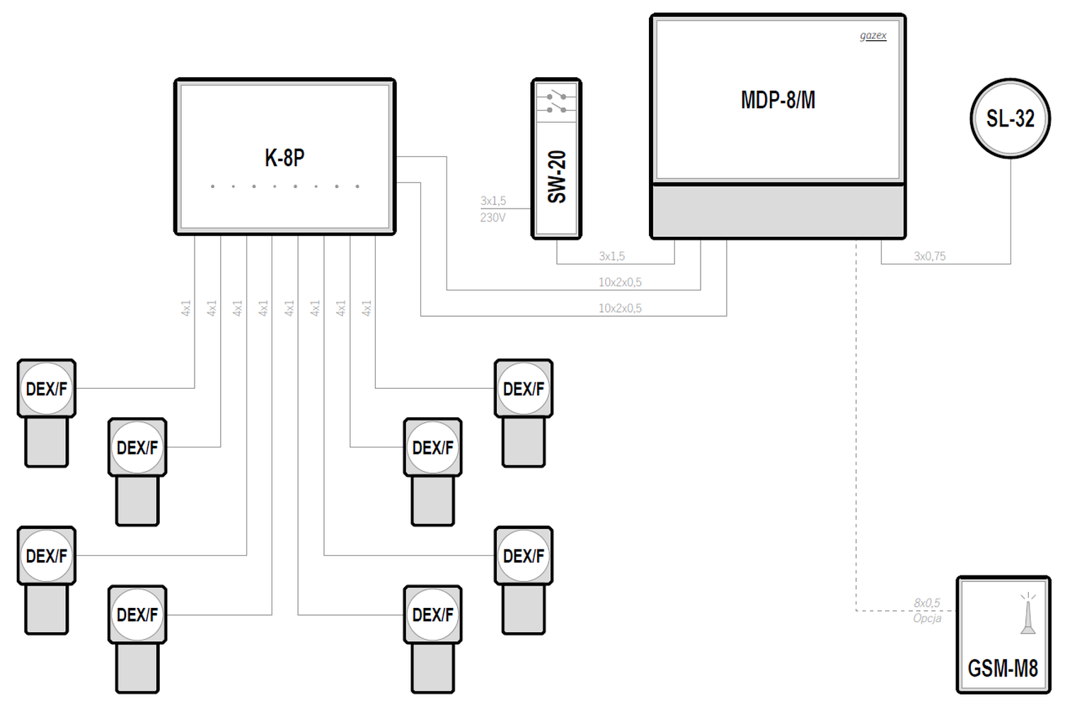
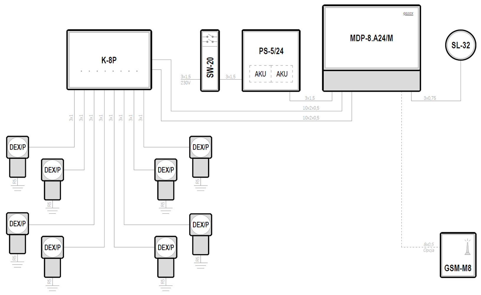
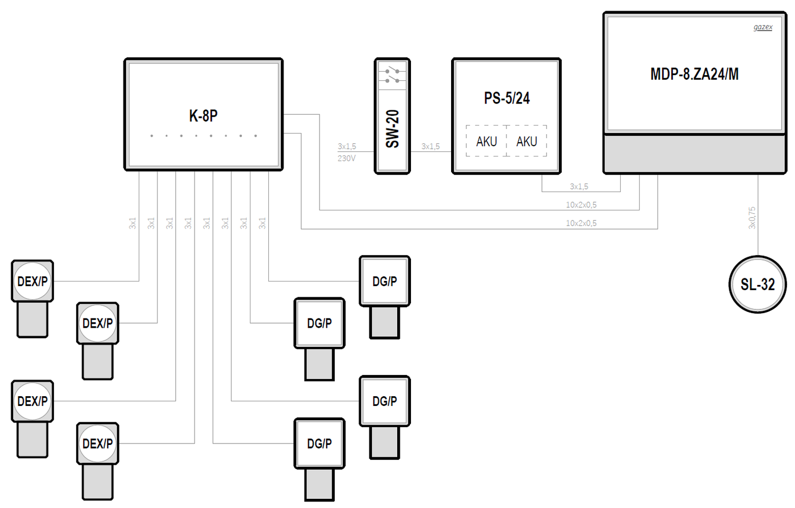
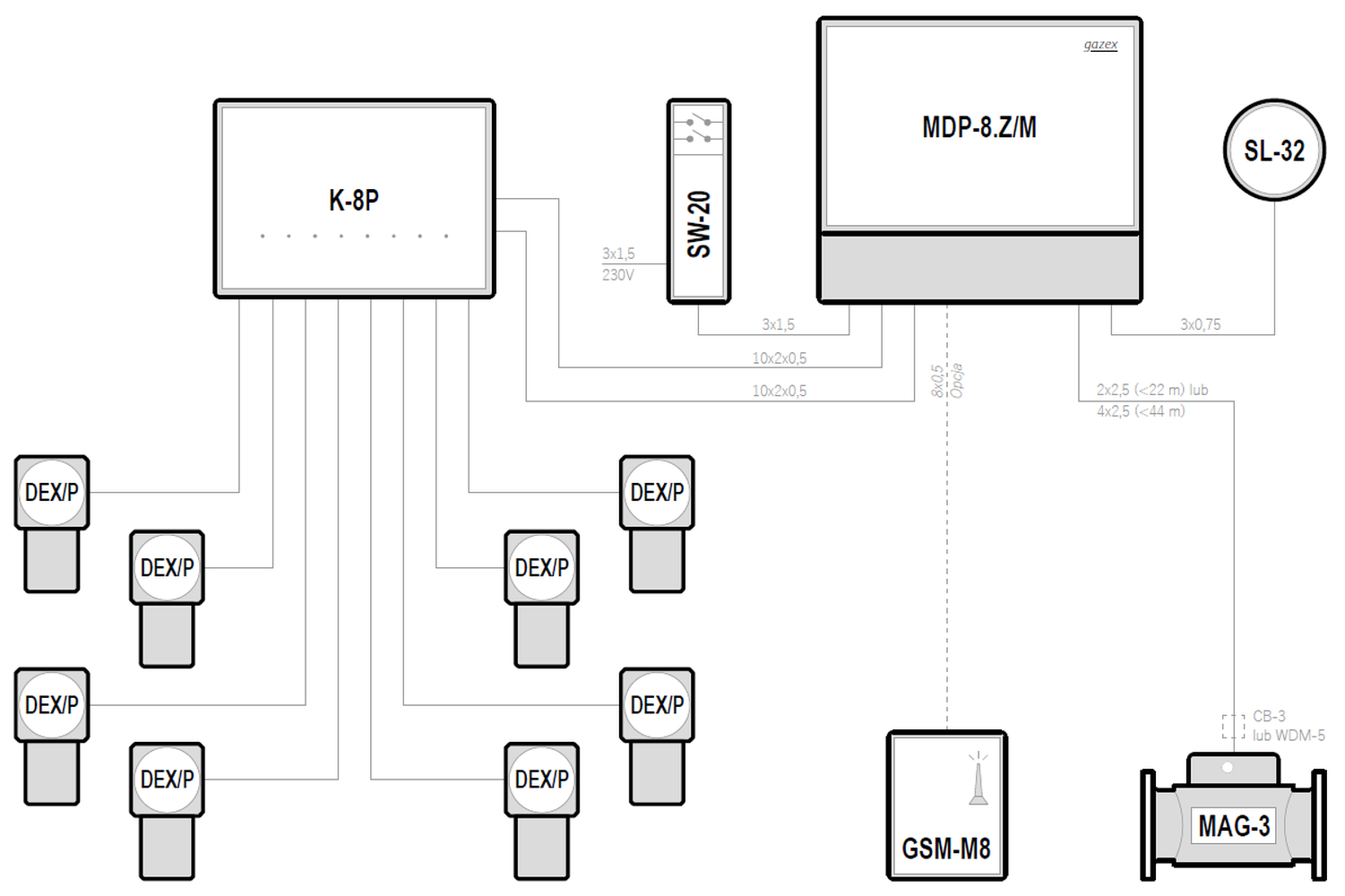
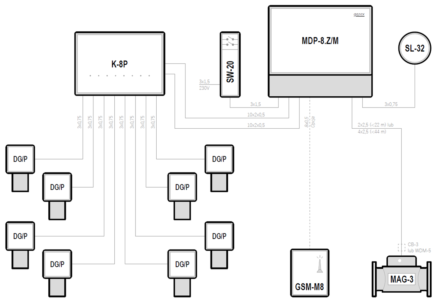
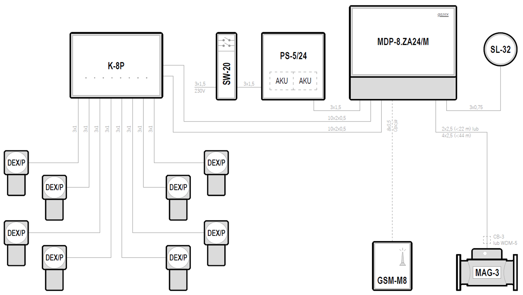
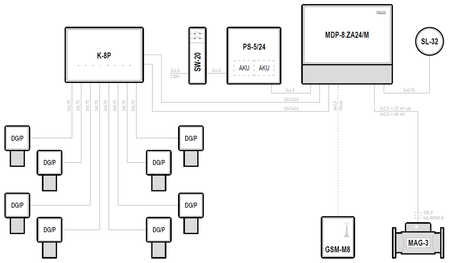
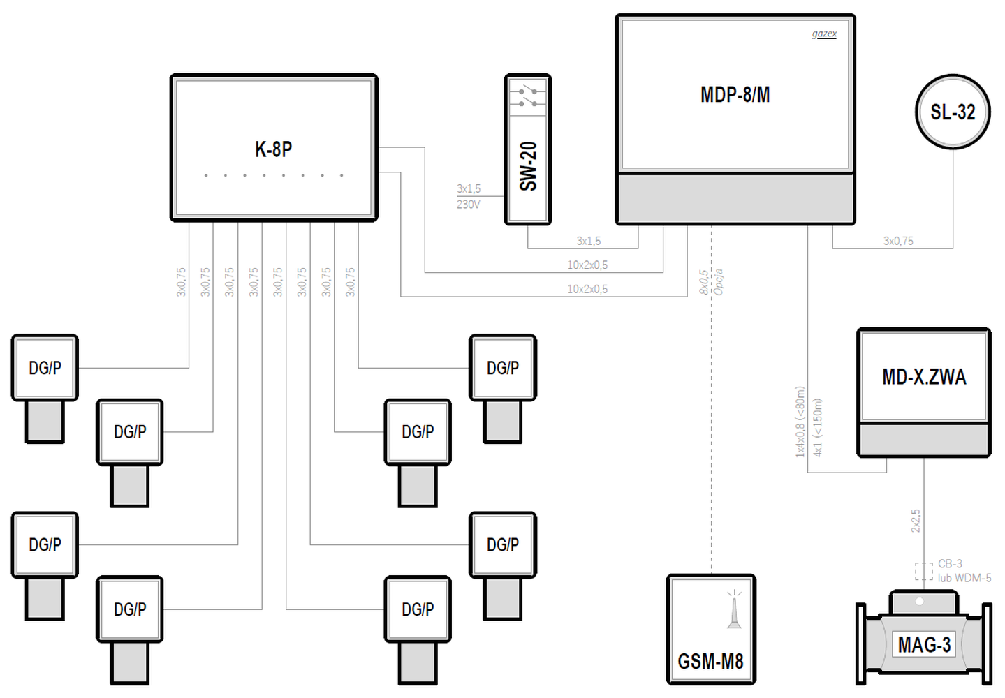
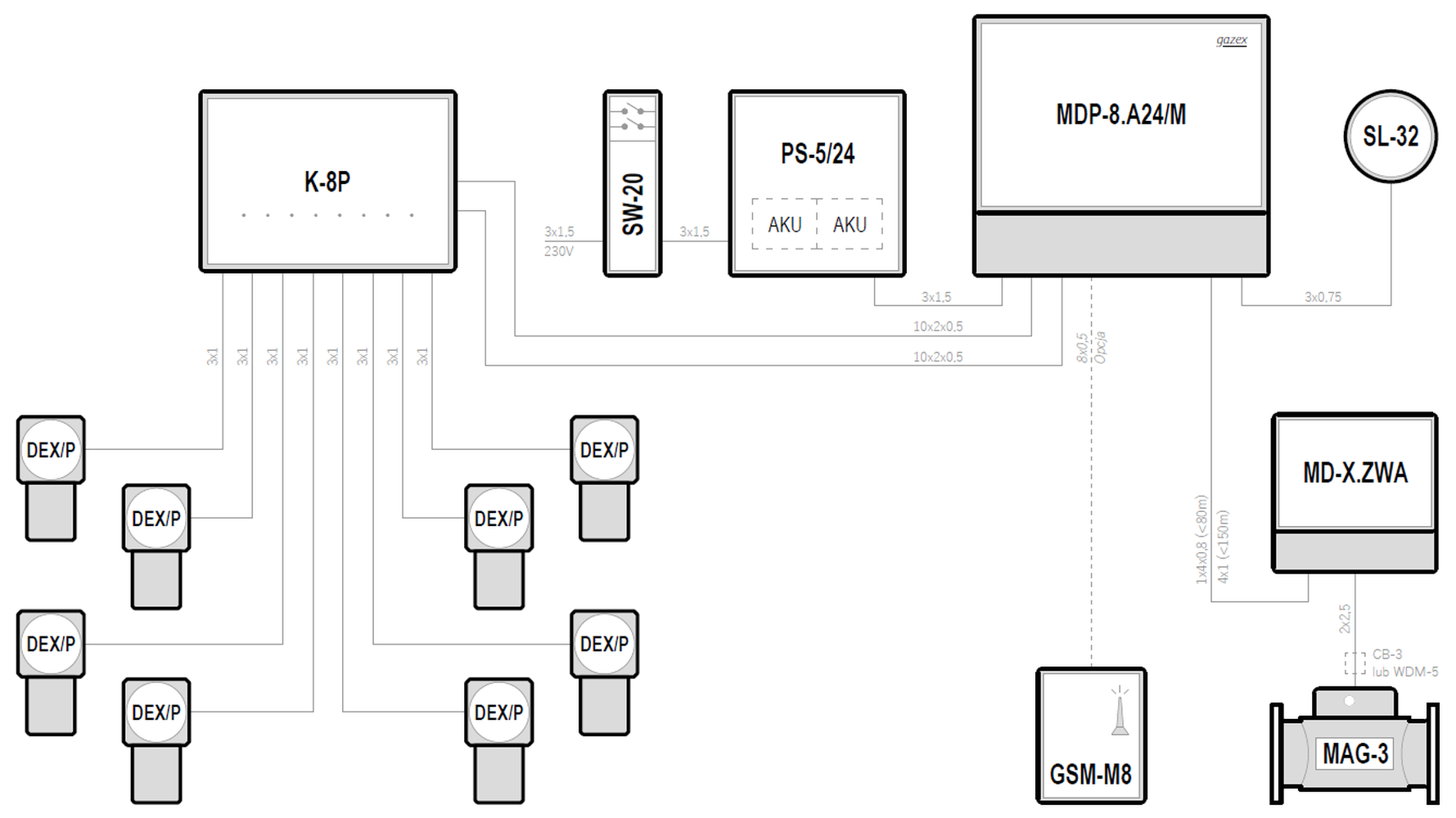
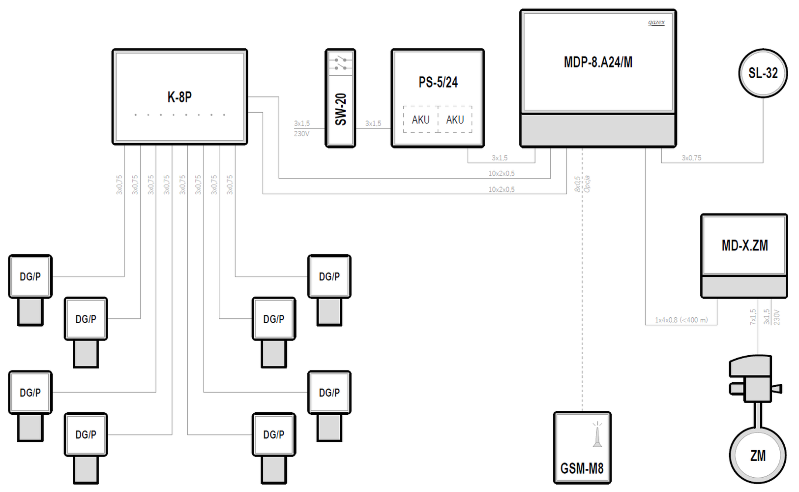
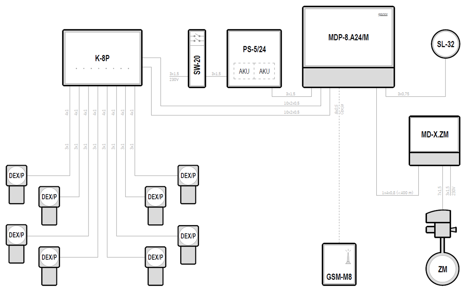
Systemy w oparciu o moduły sterujące typu MDP-8
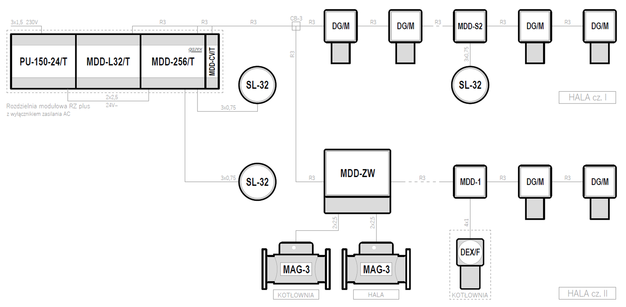
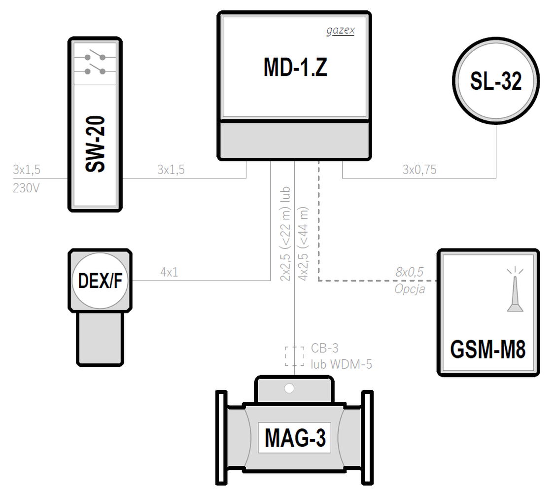
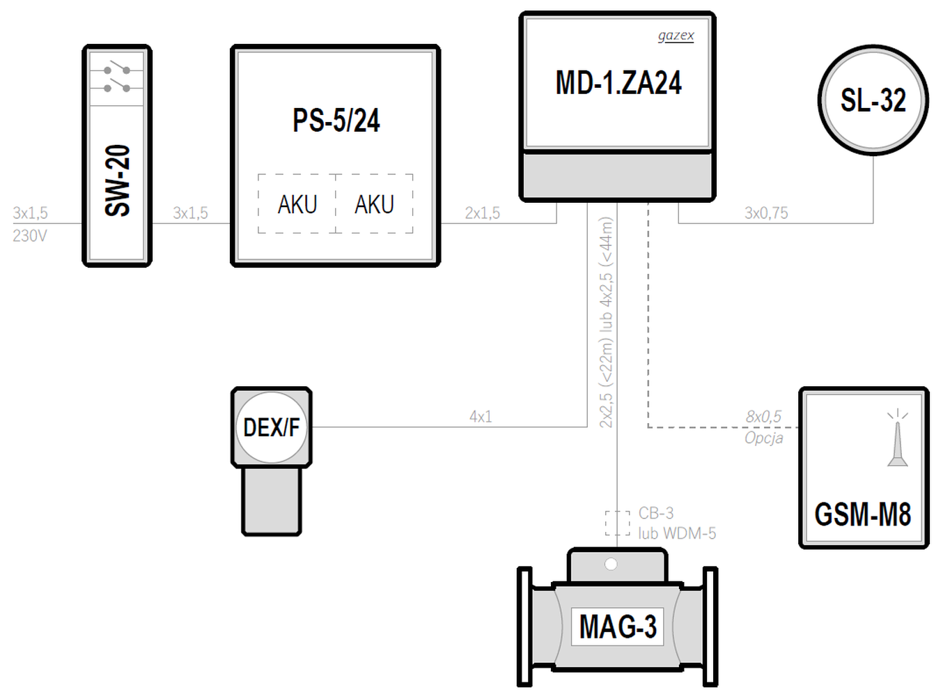
Współpraca z zaworem typu MAG-3 (sterowanie pracą zaworu bezpośrednio z modułu sterującego)
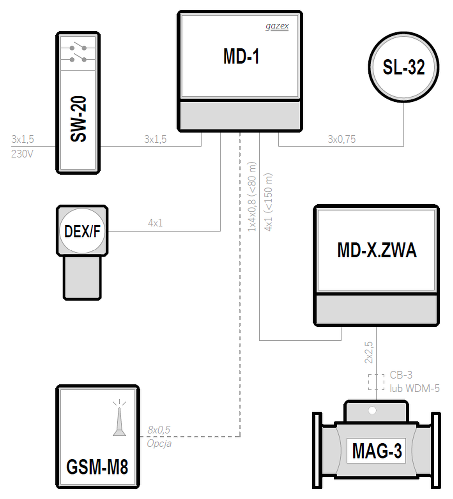
Współpraca z zaworem typu MAG-3 (sterowanie pracą zaworu za pomocą modułu pośredniczącego MD-X.ZWA)
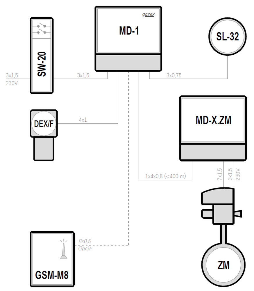
Współpraca z zaworem typu ZM
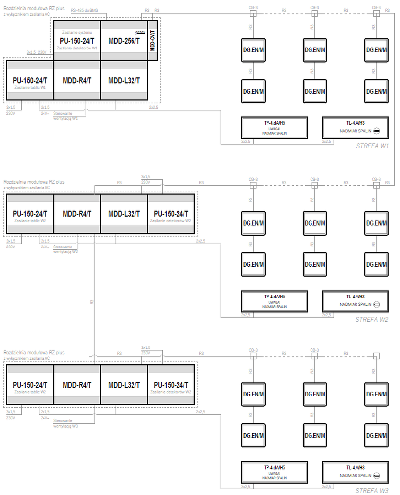
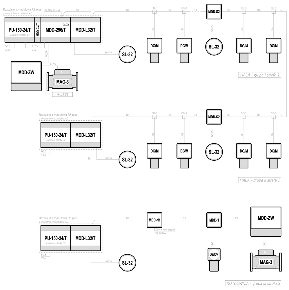
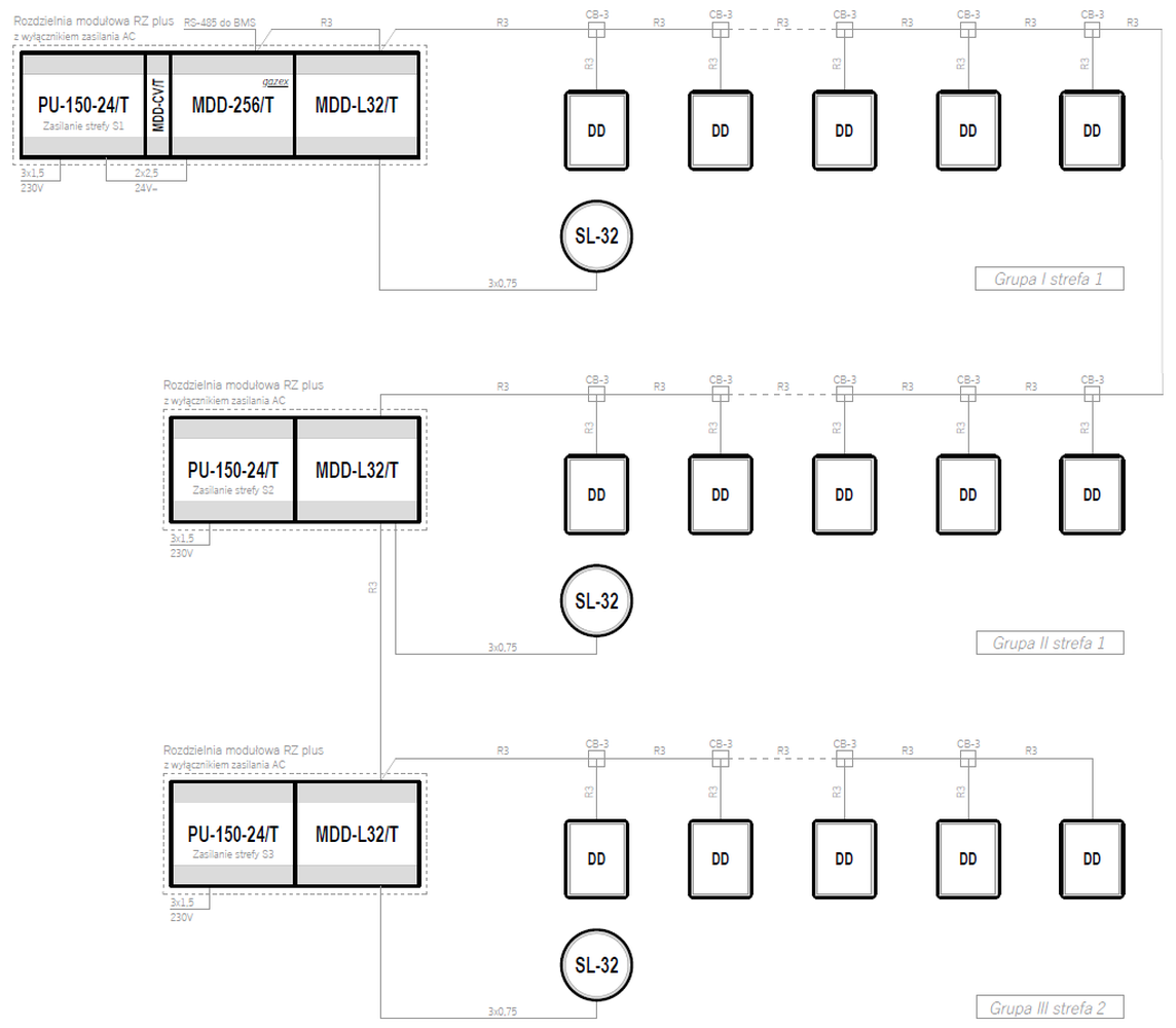
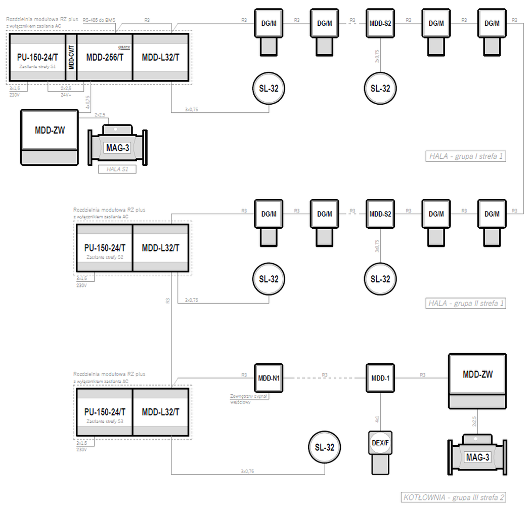
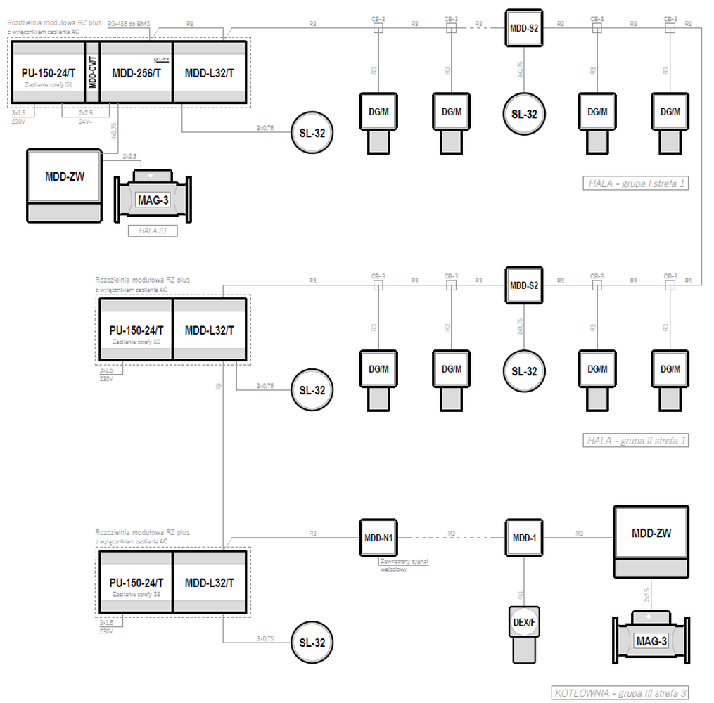
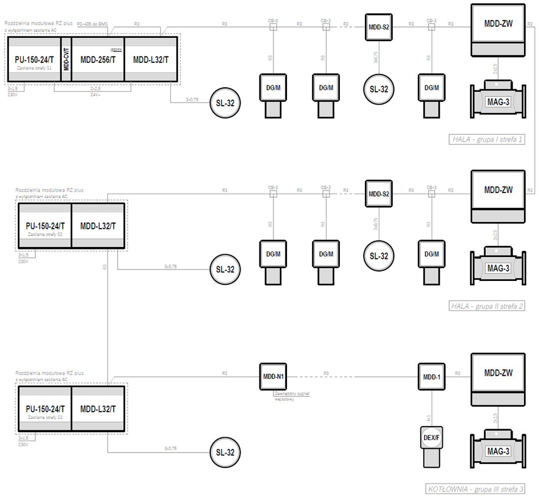
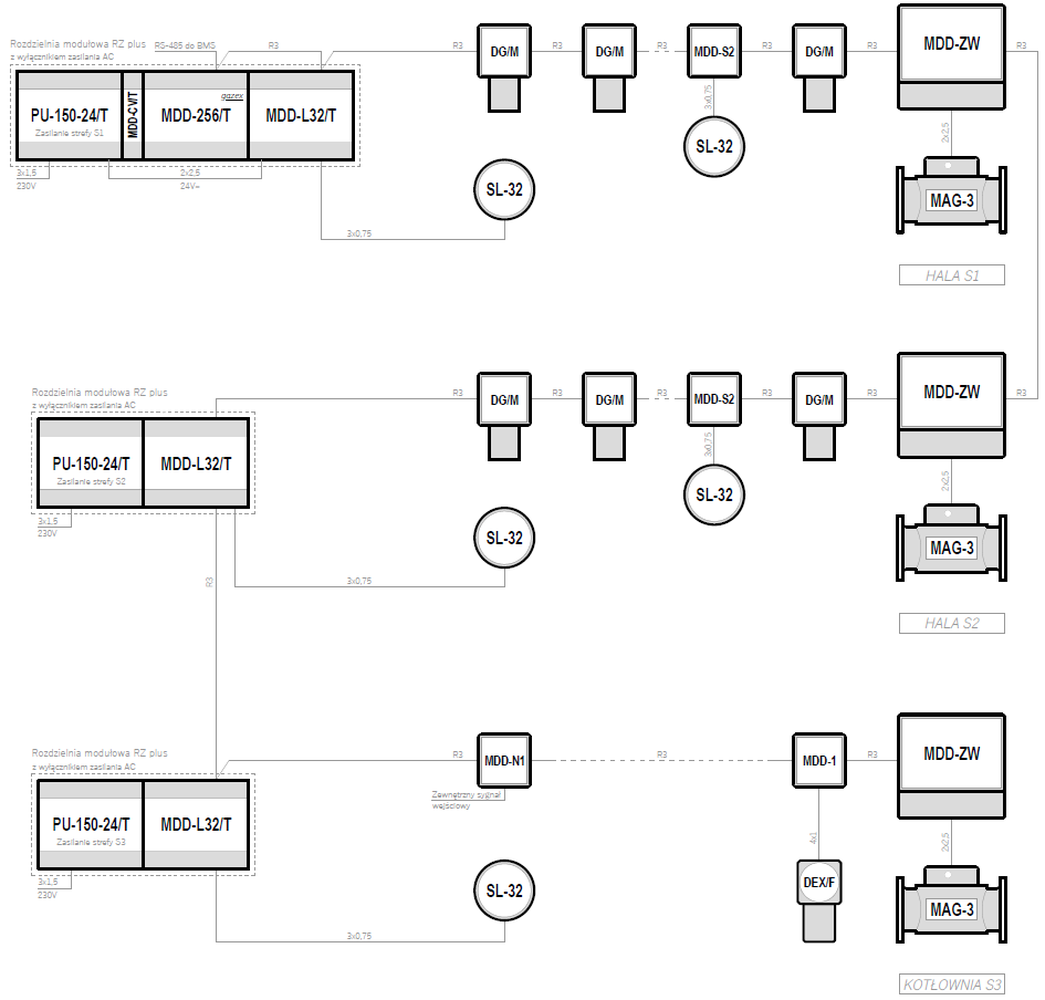
Systemy w oparciu o moduł sterujący MDD-256/T – współpraca z zaworem typu MAG-3, podział na strefy
| Supply voltage | Control unit | Maximum number of gas detectors | Types of gas detectors | Emergency power backup | |
|---|---|---|---|---|---|
| 24VDC | MDD-256/T | 224 |
DEX/F DG/M |
— | Preview PDF DWG |
| 24VDC | MDD-256/T | 224 |
DEX/F DG/M |
— | Preview PDF DWG |
| 24VDC | MDD-256/T | 224 |
DEX/F DG/M |
— | Preview PDF DWG |
| 24VDC | MDD-256/T | 224 |
DEX/F DG/M |
— | Preview PDF DWG |